
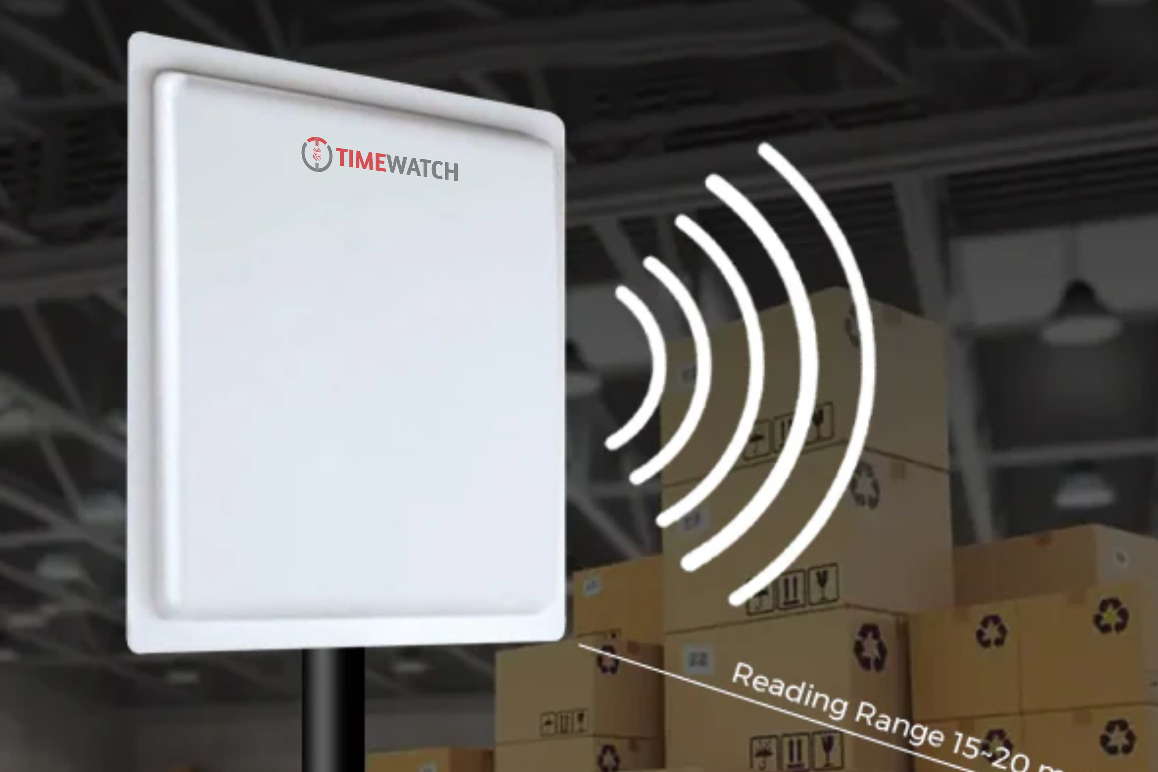
How Does a UHF RFID Reader System Work?
What Is a UHF RFID Reader System?
Unlike a card that must be tapped, a UHF system identifies things while they are moving, a vehicle approaching a gate, a pallet crossing a dock door, linen wheeled along a corridor, a tool leaving a store. That is the whole commercial point of the technology, and almost everything difficult about deploying it follows from the same property: energy that travels far enough to reach a tag at five metres also travels past the place you wanted it to stop.
There is a second property that makes UHF RFID distinctive among the technologies in this series, and it is the reason this page is organised as it is. The physics is universal, but the frequency the system runs on is not. UHF RFID occupies different sub-bands in different parts of the world, under different authorisation regimes, with different permitted radiated power. For a single-site project in one country that is a one-line procurement check. For anyone planning the same system across several countries it is the first question, and getting to it late is how projects end up with equipment that cannot lawfully be switched on where it was shipped.
How Does a UHF RFID Reader System Work?
A UHF RFID reader system works in four stages. The reader transmits RF energy through coaxial cable to one or more antennas, which radiate it into a defined volume. A passive tag entering that volume harvests enough energy to bring its chip out of reset. The chip replies by backscatter, modulating how much energy its antenna reflects so that the reflection carries its identifier. The reader decodes the returned pattern into an identifier and passes it to a controller, middleware layer or host application, which decides what the read means and what to do about it.
Transmit, harvest, backscatter, decode. Everything below is detail beneath those four verbs, and where a deployment goes wrong, it is almost always because the second and fourth are happening somewhere other than where they were intended to.
The Working Principle: Energy Harvesting and Backscatter
How a passive tag powers itself
A passive tag is an antenna printed or etched on a substrate with a small chip bonded to it. There is no battery and no oscillator. Placed in the reader's field, an alternating voltage appears across the antenna terminals. A rectifier (in practice a multi-stage charge pump) converts that to a small DC supply which accumulates on a capacitor until there is enough stored energy for the chip's logic to come out of reset and begin listening.
The consequence is worth stating plainly, because it governs every range discussion that follows: the tag exists, electrically, only while it sits in a field strong enough to power it. Read range is therefore a property of the whole installation (transmit power, antenna gain, cable loss, tag design, mounting surface, orientation and what else is in the room) rather than a property of the tag. A range figure quoted without its conditions is close to meaningless.
What backscatter actually means
Generating a carrier of its own would need far more energy than the tag has harvested, so it cannot transmit in the ordinary sense. Instead it switches its own antenna between two impedance states: in one it reflects more of the incoming energy, in the other less. Switching between them in a timed pattern imposes data onto the energy it is already bouncing back. The reader transmits and listens at the same time, sees its own carrier returning with a faint pattern superimposed on it, and decodes the bits.
This is also why the return path is the fragile one. The outgoing carrier is strong; the returning backscatter is extremely weak, because it is a modulated reflection rather than a transmission. Anything that attenuates the link attenuates it twice, and the backscatter direction is where the attenuation actually bites.
Why UHF reaches metres when LF and HF reach centimetres
LF and HF systems work by inductive coupling: the reader coil produces a magnetic field and the tag coil sits inside it like a transformer secondary. That coupling falls away very sharply with distance, which is why 125 kHz and 13.56 MHz readers operate at centimetres and need the credential presented deliberately. UHF works by radiative coupling. In the UHF range used for RFID the wavelength is of the order of tens of centimetres, short enough for a compact antenna to radiate efficiently, and the tag is illuminated by a propagating wave rather than held inside a magnetic field.
The same property that gives the range gives the problems. Radiated energy reflects off metal, is absorbed by water, diffracts around obstacles and carries on past the boundary you had in mind. Every difficult UHF installation is a consequence of that one sentence.
| Aspect | LF, 125 kHz | HF, 13.56 MHz | UHF RFID |
|---|---|---|---|
| Coupling method | Inductive, near field | Inductive, near field | Radiative, far field |
| Typical read range | A few centimetres | Around 10 cm in access use | Metres, depending on the whole installation |
| Frequency consistency across countries | Essentially consistent | Essentially consistent | Varies by region: sub-band and permitted radiated power are set nationally |
| Metal and liquid tolerance | Good | Moderate; some detuning near metal | Poor without design allowance, metal reflects, water absorbs |
| Multi-tag reading | Generally one at a time | Possible but limited | Designed for it; anti-collision resolves large populations |
| Typical use | Animal tagging, proximity cards, immobilisers | Access and smart cards, payment, NFC | Vehicle access, tolling, parking, inventory, asset and linen tracking |
Frequency choice between the three families is not a question of one band being superior. It is a question of whether the application needs a deliberate presentation gesture at close range, or identification of something moving past at a distance. Once UHF is the answer, a second frequency question opens up (one that LF and HF largely do not have) and that is the subject of the next section.
Frequency Allocation: The Defining International Specification Issue
Most technologies in vehicle access and asset management behave identically wherever they are installed. UHF RFID does not, and the difference is not a detail of performance, it is a question of what equipment may lawfully radiate, at what power, in the country where it is installed. For an international specifier this is the defining issue of the topic, and it belongs near the front of the design process rather than in a procurement checklist at the end.
Why the band is not the same everywhere
Radio spectrum is a national resource. Each country's administration decides which services may use which frequencies within its territory, and those decisions are shaped by regional coordination arrangements, by what the spectrum either side is already used for, and by history. UHF RFID is accommodated within the portion of the UHF spectrum broadly used for short-range devices, and across the world the sub-bands allocated to it fall within roughly the 860 to 960 MHz region, but the specific sub-band permitted, its width, the permitted radiated power, the channel arrangement and any requirement to hop between channels or listen before transmitting all differ between jurisdictions.
The practical consequences for a project are concrete:
- A reader is built for a band. Its transmitter, filtering and regulatory configuration are set for a particular region's rules. Many fixed readers are sold as region-specific variants for exactly this reason, and the variant is not a packaging decision.
- Permitted radiated power differs: and radiated power is one of the main determinants of read range. The same reader and antenna arrangement can therefore produce a different usable read distance in two countries without anything being wrong with the equipment.
- Channel behaviour differs. Where the local regime requires frequency hopping across a set of channels, or requires the reader to check a channel is clear before transmitting, reader behaviour in dense multi-reader installations changes with it, which affects how closely lanes can be placed.
- What is routine in one country may not be permitted in another: and the fact that a device is widely used elsewhere carries no weight with the authority that governs the installation site.
This page deliberately states no country's allocation. Allocations change, they differ between neighbouring markets, and a figure quoted on an international page is read by people for whom it is wrong. The correct source is the national radio or telecommunications authority for the country of installation, or a supplier able to provide current documentation for that market, and the figure should be confirmed in writing for the project rather than taken from any website, this one included.
Type approval, and what it does and does not permit
Alongside the band itself sits the question of authorisation. Radio equipment generally requires some form of approval, certification or registration before it may be placed on the market or operated in a given country, and the schemes differ in name, scope, process and evidence required. Three distinctions matter and are routinely confused in international projects:
- Approval is national, not universal. Evidence that a reader has been assessed against one region's radio requirements is evidence about that region. It does not confer permission elsewhere, however comprehensive the documentation looks.
- Approval of the equipment is separate from permission to operate it. Some jurisdictions additionally require the operator to hold a licence or registration for the installation, or restrict the use of certain power levels to licensed operators. A compliant reader in the hands of an unregistered operator can still be a problem.
- Approval covers a configuration. The approved state usually includes the antenna type and gain, since radiated power depends on both the reader output and the antenna. Substituting a higher-gain antenna at commissioning can take an installation outside the state in which it was assessed, this is the single most common unintentional breach in UHF installations and it happens on site, long after procurement signed everything off.
None of this is a reason to treat UHF RFID as difficult to deploy internationally. It is deployed internationally at enormous scale. It is a reason to treat the allocation and authorisation question as a design input with a lead time, rather than as paperwork that follows a technical decision already made.
How tag performance varies across the UHF range
Tags are affected by the band question too, though less absolutely than readers. A passive tag antenna is a tuned structure, and its efficiency varies with frequency. A tag optimised for one part of the UHF range performs strongly there and less well at the edges of the wider range.
- Broadband or global tags are designed to work acceptably across the whole range used worldwide, accepting somewhat lower peak performance in exchange for working everywhere. They suit multi-country deployments, tagged items that cross borders, and any programme where a single tag specification is operationally valuable.
- Region-tuned tags are optimised for a narrower portion of the range and can offer better read performance within it. They suit a fixed, single-market installation where the band is known and will not change.
- The mounting surface interacts with this. A tag's effective tuning shifts depending on what it is attached to, so a tag that performs well on glass may behave differently on plastic or against metal, which means band and surface have to be considered together rather than in sequence.
- Published range figures are stated for a band and a test condition. Comparing two tags' datasheet ranges without checking they were measured in the same part of the range, at the same power, is a comparison of test conditions rather than of tags.
What a multi-country rollout has to confirm, and in what order
Where the same system is to be deployed in several countries (a corporate estate, a logistics network, a manufacturing group standardising its gate control) the order of work matters more than any individual decision.
- 1List the countries the rollout actually covers, including any site that is likely to be added later. A site added after standardisation is the usual source of a surprise.
- 2Confirm the allocated sub-band and permitted radiated power for each: from the national authority or from supplier documentation specific to that market, in writing.
- 3Confirm the authorisation route for each: what approval or registration the equipment requires, whether the operator needs anything, and what the lead time is.
- 4Decide whether one reader variant can serve all the countries on the list: or whether the rollout needs more than one. Both are normal; discovering it late is what is not.
- 5Decide the tag strategy (a single broadband specification across the estate, or region-tuned tags per market) and make it explicitly, weighing read performance against the operational simplicity of one part number.
- 6Design the read zone and the middleware rules once: because those are genuinely portable, and re-verify the achieved read distance per country, because the permitted power may differ.
- 7Write the differences down in the design documentation: so that the next person to extend the system knows which parameters are global and which are per-country. An undocumented variation becomes a defect at the next expansion.
The underlying lesson generalises beyond RFID: confirm the applicable national regime before selecting equipment, not after. It is the same discipline that applies to machinery safety, electromagnetic compatibility and electrical installation rules in this product family, but in UHF RFID the regime does not merely govern documentation, it governs whether the equipment functions as designed at all.
Main Components of a UHF RFID Reader System
| Component | Function | What varies between specifications |
|---|---|---|
| Fixed reader | Generates the RF carrier, drives one or more antenna ports, decodes backscatter and outputs tag data over a network or control interface. | Port count, output power range, regional variant, processing capability on the reader itself, and available interfaces. |
| Integrated reader | Reader and antenna in a single housing, simpler to mount and cable, less flexible in aiming and port count. | Whether the integrated antenna's gain and polarisation suit the read zone, since neither can be changed later. |
| Antennas | Radiate the field and capture the returning backscatter. Gain and polarisation define the shape of the read zone. | Gain, beamwidth, polarisation, physical size and environmental rating. Gain forms part of the radiated power the installation is assessed on. |
| Coaxial cable and connectors | Carry RF between reader and antenna. | Cable type and length. Loss is paid on the outgoing carrier and again on the far weaker returning backscatter. |
| Passive tags | Carry the identifier and reply by backscatter. Windscreen label, hard tag, on-metal tag, laundry tag or adhesive inlay. | Construction chosen by mounting surface and environment, not by preference; broadband or region-tuned antenna design. |
| Middleware or controller | Filters, de-duplicates and time-stamps the raw read stream, turning continuous reads into discrete events. | Filtering rules available, signal-strength thresholding, direction inference, and whether rules run on the reader or on a server. |
| Host application | Access control, parking, inventory or asset platform holding the mapping from identifier to identity or item. | Where the mapping lives, how enrolment and revocation are handled, and what happens when the host is unreachable. |
| Output interface | Relay, Wiegand, RS-485, OSDP or network message into a barrier controller, door controller or server. | Protocol support, supervision of the interface, and whether a local fallback decision is possible. |
| Enclosure, power and protection | Housing, supply and surge protection for outdoor or semi-outdoor installation. | Ingress protection, operating temperature range, earthing and surge provision on long outdoor cable runs. |
How Does a UHF RFID Reader System Work Step by Step?
| Step | What happens | How it works |
|---|---|---|
| 1 | The reader energises an antenna port | An RF carrier, in the sub-band permitted where the system is installed and at a power within the local limit, is delivered through coaxial cable to the antenna. |
| 2 | The antenna radiates a field | Gain, beamwidth, polarisation and mounting angle shape that energy into a read zone covering the lane, doorway or shelf. |
| 3 | A tag enters the field | A windscreen tag, hard tag, on-metal tag or label on the vehicle or item crosses into the illuminated volume. |
| 4 | The tag harvests energy | Induced voltage is rectified to DC by a charge pump and accumulates on a capacitor until the chip powers up and begins listening. |
| 5 | The reader runs an inventory round | The reader issues a query specifying a number of reply slots, and each powered tag in the field picks one of them at random. |
| 6 | The tag replies by backscatter | In its chosen slot the tag switches its antenna impedance in a timed pattern, modulating the energy it reflects back to the reader. |
| 7 | The reader decodes the identifier | The receiver extracts the modulation from its own returning carrier and resolves the tag's identifier. |
| 8 | The tag is singulated and silenced | The reader acknowledges the tag, which then stays quiet for the rest of the round so that the remaining tags can be resolved in turn. |
| 9 | Middleware filters the stream | Repeat reads of the same identifier collapse into one event; weak reads below the signal-strength threshold are discarded as out-of-zone. |
| 10 | The host application acts | The identifier is matched against a record and an output opens the barrier, releases the door, logs the movement or updates stock. |
Steps 1 and 9 are the two the rest of this page keeps returning to. Step 1 is where the national regime enters the system, because the band and the power are not chosen freely. Step 9 is where a raw physical measurement becomes a usable business event, and a system without it produces a read stream rather than information.
How the Read Zone Is Shaped
A read zone is not a sphere around the antenna. It is a shaped volume, and shaping it deliberately is most of the engineering work in a UHF installation. The useful way to think about it is as a specification with two halves: where a tag must read, and (just as binding) where a tag must not.
Antenna gain and mounting angle
Gain does not create energy, it concentrates it. A higher-gain antenna produces a narrower, longer beam from the same transmit power; a lower-gain antenna produces a wider, shorter one. Mounting angle then decides where that beam lands. An antenna aimed straight down the lane reads vehicles far away, including vehicles you did not want. The same antenna angled downward toward the road surface a few metres ahead of the barrier reads the vehicle at the stop line and little else.
Gain is also not a free parameter in the regulatory sense, because the radiated power that matters is a function of reader output and antenna gain together. Increasing gain to extend range changes the radiated power of the installation, which is a question to settle before commissioning rather than during it.
Polarisation against tag orientation
A linearly polarised antenna concentrates energy in one plane. Range is longer when the tag's orientation matches that plane and collapses when it does not. A circularly polarised antenna sweeps the plane continuously, coupling to a tag at any rotation but at roughly half the effective range for the same power.
The choice follows directly from one question: is tag orientation predictable? A windscreen tag sits in a known, repeatable position on every vehicle, so linear polarisation is a reasonable choice and buys useful range. A hand-carried tag, a carton on a pallet, an asset tag on equipment that gets put down any way round, these arrive at any angle, and circular polarisation is the pragmatic answer even though it gives away distance. Mixed populations sometimes justify both polarisations on different antennas at the same portal, which is a legitimate design rather than an admission of indecision.
Antenna placement, transmit power and coaxial cable loss
Transmit power is set within the limit permitted where the system is installed, but the power reaching the antenna is always less than what leaves the reader, because coaxial cable has loss. That loss is paid twice (once on the outgoing carrier and again on the very weak returning backscatter) and the return path is the one with no margin to spare.
A long run between a reader mounted conveniently in a control room and an antenna at a distant gate can lose enough signal to measurably shorten read range, and the symptom is a system that works in a bench trial and disappoints on site. Reader placement is therefore a design decision rather than a convenience. Where the electronics genuinely cannot sit close to the antenna, the alternatives are lower-loss cable, or an integrated reader at the read point with only data and power running back.
Placement also interacts with the physical site. Antennas mounted where a vehicle body will shadow the tag at the moment of reading, or where a steel canopy will reflect the field into the next lane, produce problems that no amount of power adjustment resolves. Walking the site and looking at what is metal, what moves and where vehicles actually stop is worth more than any calculation at this stage.
Duplicate Reads and the Job of the Middleware
A tag inside a read zone is not read once. It is read many times per second for as long as it remains there, so a single vehicle waiting at a barrier can generate hundreds of reads of the same identifier. Deciding which of those constitute one event is the job of the middleware, not the reader.
Typical rules include a debounce window suppressing repeat reads of the same identifier for a defined period, a signal-strength threshold discarding weak reads that almost certainly came from outside the intended zone, a minimum read count before an event is declared so that a single marginal read does not trigger a barrier, and antenna-port logic inferring direction of travel from which antenna saw the tag first. Without this layer, a parking system records one vehicle arriving hundreds of times and an inventory system reports stock that is merely passing the door.
These rules are also where most of the commissioning effort ends up, because they encode what the site means by an event. They should be documented alongside the physical design and re-verified whenever lane layout, traffic flow or antenna position changes, a filtering rule tuned for one geometry is not valid for another.
How to Specify a UHF RFID System for Any Site
UHF RFID is unusually easy to buy and unusually easy to deploy badly, because the equipment works immediately on a bench and only reveals its difficulties in a real lane. The method below is deliberately independent of country, brand and product range. It is six determinations made in order, each constraining the next, and it produces a specification that can be issued to any competent supplier and answered unambiguously.
Step 1, Establish what must be identified, and at what moment
The first determination is not about hardware at all. It is a sentence describing the event the system exists to create.
- Name the object. A vehicle, a person's pass, a pallet, a returnable container, a tool, an item of linen. The object determines the tag class before anything else does.
- Name the moment. "When the vehicle reaches the stop line", "when the pallet fully crosses the dock door", "when the trolley leaves the store room". A read is only useful if it happens at a defined point, and an undefined moment is the root of most read zone problems.
- Name the speed. A vehicle at walking pace, a forklift at eight kilometres per hour and a hand-pushed trolley give the system very different amounts of time in the field, and dwell time drives antenna arrangement and reader settings.
- Name what the event triggers (a barrier opening, a log entry, a stock movement, an alert) because the consequence of a false event determines how conservative the filtering rules must be.
- Decide whether the tag alone is sufficient authority. A tag identifies the tag, not the person holding or driving the tagged thing. Where the person matters, the design needs a second factor and that belongs in the specification from the start.
Step 2, Establish the read zone boundary, including where it must not read
This is the determination that separates installations that work from installations that are endlessly adjusted. Both halves are requirements.
- Define the volume where a tag must read reliably: its length along the direction of travel, its width, and the height range the tag may occupy.
- Define the exclusion volume explicitly: the adjacent lane, the queue behind, the exit lane running in the opposite direction, the corridor outside the store room, the staging area next to the dock door. Over-reading is the commonest failure in UHF vehicle installations, and it is a design failure rather than a tag failure.
- Survey what will reflect. Steel shutters, metal canopies, parked vehicles and racking can create read points where none was intended, and a site walk finds them more reliably than a drawing.
- Consider the neighbours. Other readers at adjacent lanes need separation, synchronisation or channel planning, and how much depends partly on the channel behaviour required locally.
- Write the boundary down as a requirement, for example "must read a windscreen tag anywhere within 1 m of the stop line across the full lane width; must not read a tag in the adjacent lane or more than 6 m back in the queue".
Step 3, Establish the tag population and its mounting surfaces
Tag selection follows the surface and the environment, never preference, and the population size determines whether anti-collision behaviour is a design factor or an irrelevance.
- List the mounting surfaces: glass, painted metal, bare metal, plastic, cardboard, fabric. Each implies a different tag construction, and bare metal implies an on-metal class.
- List the environmental exposure: outdoor weather, washing, steam cleaning, abrasion, temperature extremes, chemical contact. Laundry and industrial tags exist because these conditions destroy ordinary labels.
- Estimate the simultaneous population in the read zone at the worst case, not the typical case. One vehicle is trivial; a loaded pallet is an anti-collision and shadowing problem.
- Decide the enrolment and revocation process. Tags must be issued, associated with a record, and revoked when the vehicle or asset leaves. A population with high turnover generates continuous administrative work that belongs in the design rather than being discovered later.
- Plan for replacement. Windscreen tags are generally destroyed on removal, so a replaced windscreen means a replaced tag, and the process for that should exist before it is needed.
Step 4, Confirm the allocation and type-approval regime per country
This step is the one that does not appear in the equivalent method for any other product in this family, and on a multi-country project it should be started early because it can carry a lead time.
- Confirm the permitted sub-band and radiated power limit for each country of installation, from the national authority or from supplier documentation specific to that market, in writing.
- Confirm the authorisation route: what approval or registration the reader requires there, whether the operator needs anything, and how long it takes.
- Confirm the reader variant. Establish explicitly that the variant being supplied is the one intended for that market, and record the variant in the specification rather than relying on an order line.
- Record the antenna with the reader: since radiated power depends on both and a later antenna substitution can take the installation outside the configuration that was assessed.
- Decide the tag strategy (broadband tags across the whole estate, or region-tuned tags per market) and state the reason, because the trade is between read performance and having one part number.
- Re-verify achieved read distance per country at commissioning rather than assuming the figure measured at the first site transfers to the rest.
Step 5, Decide antenna, polarisation, power and cable arrangement
Only now does hardware selection become a tractable problem, because the zone, the tags and the permitted power are all known.
- Choose polarisation from orientation predictability: linear where the tag's attitude is fixed and known, circular where it is not, both where the population is genuinely mixed.
- Choose gain and beamwidth to fit the zone: accepting that higher gain narrows the beam as it lengthens it, and that the exclusion volume constrains gain as much as the read volume justifies it.
- Set the mounting angle to put the beam on the ground where the read must happen: rather than along the lane where it must not.
- Keep the cable run short: or select lower-loss cable, or place an integrated reader at the read point. State the intended cable type and length in the specification so the loss allowance is explicit rather than assumed.
- Set transmit power as low as achieves the required read volume: not as high as permitted. Trimming power is the simplest tool against over-reading and it also eases interference between adjacent lanes.
- Specify environmental protection for outdoor equipment: enclosure rating, temperature range, earthing and surge protection on long runs, and connector sealing, which is the usual cause of gradual outdoor range loss.
Step 6, Define the middleware event rules and host interface
The last determination turns reads into events, and leaving it to commissioning defaults is how a working installation produces unusable data.
- State the debounce window: how long after a read of an identifier further reads of it are suppressed.
- State the signal-strength threshold below which reads are treated as out-of-zone, which is a second line of defence behind the physical zone shaping.
- State the minimum read count required before an event is declared, which protects against a single marginal read opening a barrier.
- State the direction logic where entry and exit must be distinguished, usually from antenna port sequence.
- State the host interface and the fallback. What happens when the host is unreachable (local decision from a cached list, refuse all, or attended operation) is a security decision that must be made deliberately.
- State what is logged: including refused reads, because a system that records only successes cannot be diagnosed later.
Writing it down: a six-line specification schedule
The six determinations condense into a schedule that can be issued with a tender and answered unambiguously. Its value is its brevity: six lines that leave no room for a bare model name to pass as an answer.
| Line | States | Example of a well-formed entry |
|---|---|---|
| 1 · Event | Object, moment, speed, consequence, and whether the tag alone is sufficient authority | "Identify tagged vehicle at the stop line at up to 10 km/h; event opens the barrier; tag alone is sufficient for staff, visitors verified by plate and intercom" |
| 2 · Read zone | Required read volume and the exclusion volume, stated as a requirement | "Read within 1 m of the stop line across the 3.5 m lane; must not read the adjacent lane or vehicles more than 6 m back in the queue" |
| 3 · Tag population | Mounting surfaces, environmental exposure, worst-case simultaneous population, enrolment and replacement process | "Windscreen tags on laminated glass; outdoor exposure; one tag in zone at a time; enrolment and revocation through the access platform; replacement on windscreen change" |
| 4 · Regime | Country list, confirmed sub-band and power limit per country, authorisation route, reader variant and matched antenna | "Four countries listed; allocation and limit confirmed in writing per country; reader variant and antenna gain recorded per site; approval evidence held by the importer" |
| 5 · RF arrangement | Polarisation, gain, mounting angle, transmit power intent, cable type and length, environmental protection | "Linear polarisation, angled down to the stop line, power trimmed to achieve the stated zone, cable run not exceeding 6 m of specified low-loss type, outdoor-rated enclosure with surge protection" |
| 6 · Event rules | Debounce, signal-strength threshold, minimum read count, direction logic, host interface and fallback, logging | "5 s debounce; reads below the stated threshold discarded; three reads minimum; direction from antenna port order; local cached list on host loss; refused reads logged" |
A supplier who can answer all six lines against a specific reader, antenna and tag has told you something useful. A supplier who answers with a read range figure has described a test condition.
Technologies Used in a UHF RFID System
- Radiative RF coupling: propagating waves in the ultra high frequency range, within the sub-band permitted where the system is installed.
- Passive energy harvesting: rectifier and charge pump circuits producing a small DC supply from the received field.
- Backscatter modulation: impedance switching at the tag antenna to impose data on the reflected carrier.
- EPC Gen2 air interface: the command set, encoding and memory structure standardised as ISO 18000-63, which is what makes tags and readers from different suppliers interoperable.
- Slotted ALOHA anti-collision: the Q algorithm resolving many tags through randomised reply slots and singulation.
- Channel management: frequency hopping or listen-before-talk behaviour where the local regime requires it, which also affects how closely multiple readers can operate.
- Antenna design: gain, beamwidth and polarisation determining read zone geometry.
- Signal-strength measurement: used by middleware as a proxy for distance, so that marginal reads can be excluded from events.
- Network and controller interfaces: TCP/IP, RS-485, Wiegand, OSDP or relay outputs into host systems.
Where UHF RFID Reader Systems Are Used
UHF RFID appears wherever something must be identified while it is moving, without a person stopping to present a credential. The site types below recur in every region:
- Vehicle access control: windscreen tags read on approach so the gate is already opening, typical at corporate campuses, industrial sites and residential communities with a stable vehicle population.
- Parking management: residents and staff identified without stopping, with visitors handled by ticket or plate recognition on the same lane.
- Tolling and dedicated lanes: high-speed identification where tag orientation is consistent and read geometry can be tightly controlled.
- Logistics and distribution centres: dock door portals reading pallets and cartons in bulk, with shadowing and anti-collision behaviour as the dominant design factors.
- Manufacturing work in progress: components identified automatically at each station, with on-metal tags where the item itself is the mounting surface.
- Warehouse and retail inventory: shelf and portal readers, and handheld readers used to inventory a room by walking through it.
- Asset and tool tracking: equipment, instruments and returnable containers located and audited without line of sight.
- Laundry and linen management: wash-resistant tags sewn into hotel and hospital linen and counted in bulk, where water absorption makes bundle geometry a design parameter.
- Personnel access at industrial gates: long-range identification alongside card or biometric verification rather than in place of it, since a tag identifies a tag.
- Document and file tracking: tagged files located in registries and archives, where dense populations of closely stacked tags are the technical challenge.
- Ports and terminals: vehicle and container movement recorded at gates, usually integrated with the terminal operating system.
TimeWatch supplies UHF RFID readers, antennas and tags internationally alongside the barrier, parking and access control equipment used with them, and maintains dedicated regional sites for several markets, see the regional guidance below.
Integration With Other Systems
- Boom barriers and gates: a valid read produces the open command, with the barrier's own safety devices governing closing. The barrier's safety behaviour is never delegated to the reader.
- Access control platforms: vehicle tag and cardholder share one database, so revoking a person closes both the door and the gate in a single action.
- ANPR cameras: plate recognition confirming the tag is on the vehicle it was issued to, and handling untagged visitors on the same lane.
- Parking management software: occupancy counting, allocation and reporting driven by entry and exit events, which is why direction logic in the middleware matters.
- Video surveillance: each read event bookmarks footage, so any passage can be reviewed from its log entry rather than by scrubbing recordings.
- Warehouse management and ERP: inventory reads reconciled against the system of record, usually after middleware has turned the read stream into movements.
- Weighbridges and dock systems: the tag identifies the vehicle so that a weighment or dock assignment is recorded against the correct trip.
- Building and estate management platforms: reader status and read-rate data surfaced alongside other plant, which is how silent degradation gets noticed.
Installation Considerations
- Define the read zone before choosing hardware. Decide where a tag must read and where it must not, then select gain, polarisation, angle and power to produce that volume. Reversing this order is the root of most unsatisfactory installations.
- Control over-reading deliberately. Reading the adjacent lane or a vehicle queued behind is corrected with polarisation choice, downward antenna angle, reduced transmit power, signal-strength thresholds and physical shielding, not by changing the tag.
- Confirm the equipment variant matches the country before installation rather than at commissioning, and keep the documentation with the project record.
- Keep the cable run short or accept a measurable range penalty, and seal connectors properly against water ingress.
- Match the tag to the surface: and trial it on the actual material in the actual position before committing to a quantity.
- Survey for reflective structures: metal shutters, steel canopies, racking and parked vehicles can create read points nobody intended.
- Separate or synchronise adjacent readers so that neighbouring lanes do not interfere with each other.
- Protect outdoor electronics with correct enclosure rating, earthing and surge protection on long cable runs, which matters particularly in regions with high lightning incidence.
- Commission with real traffic at the speeds, orientations, loads and vehicle mix the site will actually see, not with a tag held up by hand.
- Record the commissioned configuration (power setting, antenna angle, filtering rules) so a replacement unit can be set up identically and so later changes are visible as changes.
Maintenance Considerations
- Inspect antenna mounting and aim. An antenna knocked by a vehicle or loosened by vibration changes the read zone silently, and nothing about the system announces it.
- Check coaxial connectors for water ingress and corrosion, the usual cause of gradual outdoor range loss over a season rather than a sudden failure.
- Review read statistics periodically. A falling read rate almost always indicates a physical change (aim, cable, tag condition or a new obstruction) rather than a software fault.
- Replace damaged, delaminated or sun-degraded tags, and re-tag vehicles whose windscreen has been replaced.
- Re-verify middleware filtering rules after any change to lane layout, traffic flow, antenna position or reader placement.
- Keep firmware current where the supplier supports it, and keep the recorded configuration up to date so a replacement unit can be commissioned identically.
- Re-check the equipment documentation when a site is added in a new country, since the variant and authorisation question returns with it.
Benefits and Limitations
Benefits
- Identification without stopping, aligning or presenting a credential, which is what keeps a lane flowing at peak.
- Many tags resolved in a single pass, making bulk counting practical rather than theoretical.
- Passive tags need no battery and no servicing, so a large tagged population carries no recurring maintenance per tag.
- No line of sight required, so a tag inside a carton or behind a windscreen still reads.
- Events feed directly into access control, parking, inventory and asset systems with a timestamped record.
- A standardised air interface means tags and readers from different suppliers interoperate, which protects the tagged population from being tied to one reader supplier.
Limitations and considerations
- The tag identifies the tag, not the person. A windscreen tag authorises the vehicle whoever is driving it. Where the individual matters, pair it with card, biometric or plate verification.
- Read zones leak. Radiated energy does not stop at a painted line, and containing it is genuine design work at every site rather than a setting.
- Metal and liquid degrade performance unless tag type and mounting are chosen for them, and a trial on the real surface is the only reliable check.
- Range figures are conditional: assuming favourable orientation, free space, a particular part of the UHF range and full permitted power. They rarely transfer between sites, and may not transfer between countries.
- The frequency regime is national. Equipment permitted in one country may not be permitted in another, permitted power differs, and an international rollout has a confirmation step that a single-market project does not.
- Middleware is not optional. Without filtering, the raw read stream is unusable as an event source.
- Specifications vary by model. Read range, antenna ports, supported protocols, output interfaces, channel behaviour and environmental rating differ between readers and should be confirmed against the datasheet and validated on site.
UHF RFID vs ANPR: What Is the Difference?
| UHF RFID | ANPR | |
|---|---|---|
| What it identifies | A tag issued by the site operator | The number plate already on the vehicle |
| Needs prior enrolment | Yes, a tag must be fitted and associated with a record | No, any plate can be read, subject to recognition performance |
| Main sensitivity | Tag orientation, metal, liquid and read zone containment | Plate condition, camera angle, illumination, vehicle speed and plate format |
| International variability | Frequency allocation and authorisation differ by country | Plate formats, fonts and dimensions differ by country, which affects recognition |
| Typically suited to | Regular, repeat vehicles with a stable population | Visitors, occasional traffic and populations that cannot be tagged |
The two are complements rather than alternatives, and many sites run both on one lane with the controller accepting authorisation from either source. It is also a useful pairing for verification: the plate confirms that the tag is on the vehicle it was issued to, which closes the one gap that a tag-only system cannot close by itself.
Regional Guidance: India, Saudi Arabia and the UAE
This page is written to be useful anywhere, which is precisely why it does not state any country's frequency allocation. That figure is genuinely local, it changes, and a number quoted on an international page is wrong for most of the people reading it. Local availability, local authorisation processes, local support arrangements and local installation practice are local in the same way.
For three markets, TimeWatch maintains dedicated regional sites with locally relevant versions of this guidance, including the allocation and procurement position for that market, local product availability and local support. If you are specifying in one of them, start there rather than here:
Readers elsewhere are in the right place. The physics, the read zone method, the tag selection logic and the six-step specification schedule on this page all transfer anywhere, what you supply is the allocation and authorisation position for your own country, confirmed with the national authority or a supplier able to document it for that market, and the method does the rest.
Frequently Asked Questions
How does a UHF RFID reader read a tag that has no battery?
The reader's antenna radiates RF energy into the read zone. The tag's antenna picks up part of that energy and a rectifier circuit inside the tag converts it to a small DC supply that powers the chip. The chip then replies by changing how much energy its antenna reflects back. The tag never generates a signal of its own, so it needs no battery, but it only works while it sits in a field strong enough to power it.
What is backscatter in RFID?
Backscatter is the method a passive tag uses to reply. Instead of transmitting, the tag switches its antenna between two impedance states, reflecting more energy in one and less in the other. Switching in a timed pattern imposes the tag's data onto the energy already bouncing back to the reader, which transmits and listens at the same time and decodes the pattern from its own returning carrier.
Why does UHF RFID use different frequencies in different countries?
Because radio spectrum is allocated nationally. Each country's administration decides which services may use which frequencies in its territory, shaped by regional coordination and by what the neighbouring spectrum already carries. UHF RFID is accommodated in different sub-bands in different regions, with differing permitted radiated power and channel rules. The applicable allocation must be confirmed with the national authority for the country of installation, because it differs between markets and changes over time.
Can I use a UHF RFID reader bought in one country in another country?
Not as a matter of course. Readers are built and authorised for a particular region's band and power rules, and many are sold as region-specific variants. Approval obtained in one country says nothing about permission in another, and some jurisdictions also require the operator to be registered. For any installation outside the market a reader was supplied for, confirm the permitted sub-band, the power limit and the authorisation route before the equipment is ordered.
Does the frequency band affect how well a tag reads?
Yes. A passive tag antenna is a tuned structure and its efficiency varies across the UHF range. Broadband or global tags are designed to work acceptably across the whole range used worldwide, trading some peak performance for working everywhere, while region-tuned tags perform better within a narrower portion. The mounting surface shifts a tag's effective tuning as well, so band and surface should be considered together rather than one after the other.
How far can a UHF RFID reader read a tag?
Several metres is typical for vehicle access with a windscreen tag, but range is a property of the whole installation rather than of the tag. Transmit power within the locally permitted limit, antenna gain, polarisation, mounting angle, coaxial cable loss, tag construction and the surface the tag is mounted on all affect it. Published figures are measured under favourable conditions and should be validated on site.
Why does an RFID tag not read properly when it is stuck on metal?
A standard tag antenna is designed to resonate in a particular electrical environment. Metal changes its impedance and reflects the field away, so the tag is detuned and may read poorly or not at all. On-metal tags exist as a separate product class for this reason: they include a spacer or a ground plane so that the antenna works correctly against a conductive surface.
Does water affect UHF RFID?
Yes. At UHF frequencies water absorbs RF energy strongly, so tags on liquids, damp materials, laundry bundles or close to a human body read at considerably shorter distances than the same tags in free air. Where liquid is unavoidable, bundle geometry, stacking arrangement and tag position matter as much as the tag specification, and a portal that reads a test load may fail on a full one.
How does a reader read many tags at the same time?
EPC Gen2 readers use a slotted ALOHA-based anti-collision protocol, controlled through its Q parameter. The reader announces a number of reply slots and each powered tag picks one at random. A slot containing a single tag produces a clean reply, which the reader acknowledges before silencing that tag for the rest of the round. Collisions are retried and the slot count is adjusted between rounds until the whole population has been resolved one tag at a time.
Why does the reader pick up vehicles in the next lane?
Because radiated energy does not stop at a lane marking. Over-reading into an adjacent lane, or reading a vehicle queued behind, is the most common problem in UHF vehicle installations. It is corrected by changing antenna polarisation, angling the antenna down toward the point where the read should happen, reducing transmit power, applying a signal-strength threshold in the middleware and adding physical shielding. Changing the tag rarely helps.
Why is the same tag reported many times?
A tag inside the read zone is read many times per second for as long as it stays there, so one vehicle arrival can produce hundreds of reads of the same identifier. Middleware decides which reads form a single event, using a debounce window, a minimum read count, a signal-strength threshold and antenna-port logic for direction. Without that filtering layer the raw read stream cannot be used directly as an event source.
