
How Does a Toll Barrier System Work?
What Is a Toll Barrier System?
A toll barrier system is not a single device. It is a lane of cooperating subsystems (sensing, identification, computation, actuation and audit) in which the moving arm is only the visible final step. The arm is also the least interesting part of the design. What makes a toll lane difficult is that it must produce a defensible record: which vehicle passed, what class it was judged to be, what was applied, and on what authority the arm lifted.
That audit requirement is the thread running through everything below. It explains why a lane carries classification sensors as well as a reader, why a camera photographs vehicles that have already paid, and why the lane holds a complete transaction locally even when it is talking to a central system in real time.
One framing point before the detail. The equipment is broadly similar everywhere; the scheme it serves is not. Charging basis, vehicle class definitions, who may be pursued for an unpaid passage, and how money moves between operators are national constructions. A specification written without first establishing those is a specification for a lane that cannot be commissioned.
How Does a Toll Barrier System Work?
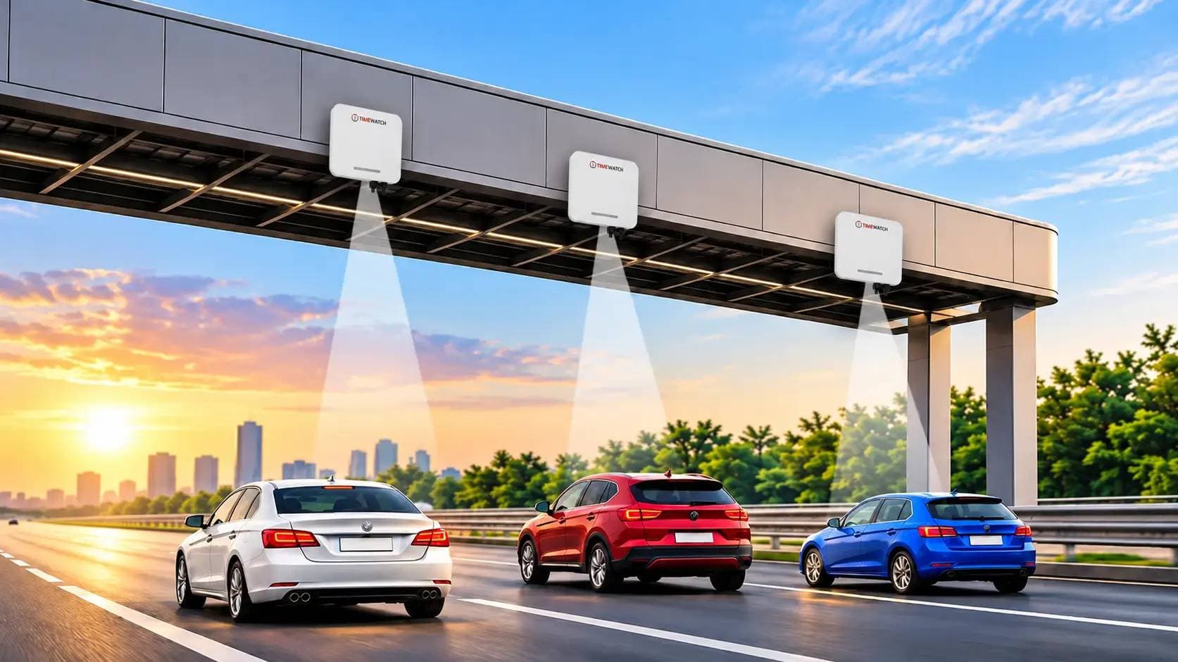
A toll barrier system works in five stages. Sensors classify the vehicle from its physical characteristics. A reader or camera identifies it from a transponder, an on-board unit, a plate or an issued ticket. The lane controller computes and validates the charge for that class against the identified account. On a valid transaction it releases the barrier, which opens, allows the vehicle through and closes behind it. The transaction is then logged and forwarded to the central system for settlement and, where the transaction failed, for enforcement.
Classify, identify, validate, release, log. Everything else on this page sits beneath those five verbs, including the specification method, which is most usefully understood as a series of questions about how each of the five is to be performed, under whose rules, and how often per hour.
Free-Flow vs Barrier-Controlled Tolling: The Central Architectural Distinction
Before any equipment question, there is an architectural one: does the vehicle have to stop, or not? This single decision determines the civil works, the identification technology, the enforcement burden and the achievable throughput, and it is the distinction that most readers arrive without having made explicit.
| Aspect | Barrier-controlled lane | Free-flow (open road) charging |
|---|---|---|
| Vehicle behaviour | Slows or stops at a defined lane; passage is physically withheld until the transaction completes | Passes at road speed beneath a gantry; nothing is physically withheld |
| Enforcement model | Primarily preventive, a failed transaction does not open the arm | Entirely post-event, an unidentified or unpaid passage becomes a violation case |
| Identification demand | Read at low speed over a short, well-defined zone | Read at road speed across multiple lanes, with lane-straddling and overtaking vehicles |
| Classification demand | Vehicle crosses sensors in a known order at low speed | Classification from overhead or roadside sensing at speed, generally harder and more equipment-intensive |
| Throughput ceiling | Set by lane service time, the barrier cycle is part of the critical path | Set by the road itself, not by the charging system |
| Civil works | Plaza footprint, lane channelisation, queueing space, exception bays, operator positions | Gantry foundations and equipment cabinets; no plaza |
| Typically selected where | Charging must be enforced at the point of passage, account penetration is partial, or exceptions must be resolved locally | Account and transponder penetration is high, plate data access supports post-event enforcement, and interrupting traffic is unacceptable |
| What usually decides it | Whether the scheme has a workable legal and data route to pursue an unpaid passage after the fact | Same question, answered the other way |
The honest summary is that free-flow charging moves the problem rather than removing it. It removes the queue and the plaza, and in exchange it transfers the entire burden of collection onto identification accuracy and a post-event enforcement process that must be legally supported in that jurisdiction. Where it is not (where an operator cannot reliably obtain keeper details for an unidentified plate, or cannot pursue a foreign-registered vehicle) a barrier-controlled lane remains the architecture that actually collects.
Many schemes run both, and the hybrid is often the most practical answer: free-flow on high-volume corridors where account penetration is high, barrier-controlled lanes at entry and exit points, at crossings with a high proportion of occasional or foreign traffic, and anywhere classification disputes need to be settled with the vehicle still present.
The Toll Lane Sequence Step by Step
| Step | What happens | How it works |
|---|---|---|
| 1 | Vehicle enters the lane approach | An entry loop or presence sensor registers arrival and the lane controller opens a new transaction record. |
| 2 | Vehicle is classified | Classification sensors determine the charging class from physical characteristics, axle count, height, silhouette, length or weight, depending on what the scheme's class schedule is defined on. |
| 3 | Vehicle is identified | A roadside or gantry reader interrogates the transponder or on-board unit on the approach. Mixed and manual lanes may use a ticket, card or operator entry instead. |
| 4 | Charge is computed | The controller applies the scheme's schedule for the determined class, together with any journey, time-of-day, exemption or return rule held in the lane configuration. |
| 5 | Transaction is validated | The identifier is checked against account status held locally: valid, active, not on the exception list, and able to settle the charge. |
| 6 | Barrier is released | The controller issues the open command and updates the lane signal and driver display. |
| 7 | Vehicle passes | An exit loop and photocell confirm the vehicle has moved clear of the barrier zone. |
| 8 | Barrier closes | The arm lowers once the lane is confirmed clear, timed so a following vehicle cannot pass on the same transaction. |
| 9 | Transaction is logged | Class, identifier, amount, timestamp, lane, plate read and evidential images are written locally and forwarded to the central system. |
| 10 | Exceptions are routed | Where the sequence failed (no read, account unable to settle, listed identifier, disputed class) the transaction is routed to the lane's exception path and, where applicable, into violation processing. |
Step 10 is the one that decides whether a plaza flows or queues, and it is the step most often left undesigned. A lane that handles its successful transactions beautifully and has nowhere to put a failed one will block on the first failure of the morning peak and stay blocked behind it.
Note also that steps 2 and 3 are independent and can disagree. The sensors report what the vehicle physically is; the identifier reports what it was registered as. Reconciling that disagreement (in the lane, at the operator position, or later in audit) is a defined procedure in any competent scheme, and the lane must retain the classification evidence and images to support it.
Main Components of a Toll Barrier System
| Component | Function | What varies between specifications |
|---|---|---|
| Gantry or roadside mounting structure | Carries the reader antennas and cameras in the geometry the read zone requires. | Overhead span versus side mounting, height, and whether the structure must also carry variable signage and lighting. |
| Transponder reader and antennas | Interrogates the vehicle's transponder or on-board unit and returns its identifier to the lane controller. | Air interface and frequency band, which are set nationally; antenna count, polarisation, power setting and read zone shaping. |
| Classification sensors | Determine the charging class from physical characteristics. | Which characteristics the scheme's class schedule is defined on, and therefore which sensor set is required. |
| Plate recognition and evidential cameras | Capture the plate and an overview image of every vehicle entering the lane. | Plate formats to be recognised, capture rate required, image package the enforcement process accepts. |
| Lane controller | Sequences the transaction, applies the schedule, drives the barrier and communicates with the central system. | Local autonomy during host outage, exception-list capacity, interface protocols, audit log retention. |
| Barrier | The physical release mechanism, generally a high-duty unit given toll cycle counts. | Duty rating after derating, arm length and section, opening and closing time, safety device set. |
| Driver signalling | Lane signal, status display and overhead lane-mode signage so drivers select correctly before committing. | Message set, language and symbol conventions, and visibility distance on the approach. |
| Operator position | Staffed terminal in manual and mixed lanes: exception handling, manual class override, issued credentials. | Whether the scheme requires an attended fallback at all, and how many positions per plaza. |
| Central system and clearing interface | Aggregates lane transactions, distributes account and exception data, produces audit and settlement output. | Settlement model, interoperability obligations, data retention and reporting duties under the scheme. |
| Power conditioning and backup | Keeps the lane live through supply disturbance. Losing power mid-transaction creates a reconciliation problem, not merely an outage. | Supply voltage and frequency vary by region; autonomy period and surge provision vary with exposure. |
The gantry, the reader and the read zone
The reader is mounted where the transponder can be seen. A windscreen-mounted transponder faces upward and forward, which is why overhead mounting is conventional; an on-board unit mounted elsewhere in the vehicle, or a headlamp-mounted tag, changes the geometry. The read zone has to be large enough that identification completes before the decision point, and tight enough that it does not capture a transponder in the adjacent lane or one queueing behind.
Cross-lane reads are a genuine failure mode at closely spaced lanes, and they are managed through antenna polarisation, power trimming, physical shielding and read-zone shaping during commissioning. The workable arrangement depends on the reader model and the lane geometry, so it is established by test on site rather than assumed from a datasheet.
Vehicle classification sensors
Classification exists because the charge depends on what the vehicle is. Axle counters (treadles, piezoelectric strips or similar devices set into the surface) detect each axle crossing, and better implementations distinguish a raised axle from a loaded one. Laser scanners and light curtains measure height, silhouette and length. Loop signature electronics analyse the shape of the inductance change as the vehicle crosses, which carries information about length and undercarriage. Weighing sensors are used where the schedule is defined on mass.
The combination required follows directly from the class schedule, not from preference. A scheme that charges on axle count needs reliable axle detection; a scheme that charges on height over the first axle needs a profiler positioned to measure exactly that; a scheme that charges on registered category needs a trustworthy route to the registration record rather than more sensors. Specifying a sensor set before reading the class schedule is the most common way to buy equipment that cannot answer the question being asked of it.
Plate recognition as the enforcement layer
This is the point most often misunderstood, and it matters more in some architectures than others. In a barrier-controlled lane with transponder identification, plate recognition is not how the vehicle is identified for charging. The transponder is. Plate recognition runs in parallel, capturing every vehicle whether or not the transponder reads, and serves enforcement and reconciliation: recovering the charge after a failed read, evidencing accounts unable to settle, and identifying vehicles that run the lane without a valid transaction.
In a free-flow architecture the position changes. Where no transponder is present, the plate is the identification, and the entire collection depends on recognition accuracy and on a legal route from plate to payer. That route is jurisdictional, and it is the single assumption most worth testing early: a scheme whose enforcement depends on obtaining keeper details cannot function where that data is not reliably available, including for vehicles registered elsewhere.
Recognition performance is a function of camera angle, mounting height, stand-off, illumination, vehicle speed, plate condition and (importantly for an international reader) plate format. Dimensions, character sets, fonts, colours and mounting conventions vary enormously between countries, and a recognition engine tuned for one plate population will not necessarily perform the same way on another. Any specification should state which formats must be recognised and at what capture rate.
Lane controller, barrier and driver signalling
The controller is the only component that sees the whole transaction, which is why it, rather than the barrier, holds the timing, exception and safety logic. The barrier itself behaves like any other powered boom barrier: a safety loop beneath the arm inhibiting closure while a vehicle is present, a photocell across the lane that stops and reverses on obstruction, and obstruction detection at the drive. What differs from a commercial gate is duty rating and the tightness of the timing window.
Driver signalling is part of the engineering, not decoration. A driver who cannot tell from the approach which lanes accept which method will commit to the wrong lane, and recovering from that (reversing, or being processed manually) is far more disruptive than the few seconds the signalling would have saved.
How Vehicles Are Identified Electronically
Passive UHF RFID transponders
A passive UHF transponder carries an identifier and no battery. The reader radiates RF energy; the transponder harvests enough to power its chip and backscatters its identifier. Read distances of several metres allow identification while the vehicle is still approaching. Mounting is typically a windscreen label or a hard-cased tag, and because it is passive the transponder has no service life limit imposed by a battery.
Two constraints travel with this technology anywhere. First, the permitted UHF band and radiated power limits are allocated nationally and differ between regions, so readers and transponders must be the variant permitted in the country of installation, a procurement check, not an afterthought. Second, fitment governs read reliability more than the equipment does: a transponder behind a metallised or heat-reflective windscreen reads unreliably or not at all, because the coating attenuates RF energy in both directions. A lane with a poor read rate should be checked for fitment before the reader is suspected.
DSRC microwave transponders and on-board units
Dedicated short-range communication systems use a microwave link, commonly in a band around 5.8 GHz in several regions, between a roadside unit and an on-board unit in the vehicle. On-board units are typically battery-powered and support a two-way exchange rather than a simple identifier return, which allows the unit to hold account state, acknowledge a transaction and display a status to the driver.
The architecture is widely used where schemes require the vehicle to carry evidence of the transaction, or where heavy goods vehicle charging demands a richer exchange than an identifier. It is also the layer where cross-border interoperability arrangements are usually built, because a two-way protocol can carry the data a foreign operator needs. The practical specification points are band and protocol variant, on-board unit battery life and replacement logistics, and which roadside unit families the scheme has already standardised on.
Plate-based identification
Plate recognition identifies the vehicle without anything fitted to it, which makes it the only method available for occasional, visiting and foreign traffic. It is the primary identification route in video tolling and the universal fallback everywhere else. Its limitations are the ones set out above: format sensitivity, dependence on capture geometry and illumination, degradation with plate condition and obscuration, and dependence on a legal route from plate to payer.
A well-designed scheme treats plate identification as a tier rather than a technology (first choice for some traffic, backstop for the rest) and specifies a capture rate and an evidential image package explicitly, rather than assuming a recognition rate quoted under test conditions will survive a wet night.
Satellite-based and declared-journey charging
Some charging schemes, particularly those applied to heavy goods vehicles over a road network rather than at defined points, use a satellite positioning receiver in an on-board unit to determine which charged sections the vehicle has used, reporting over a mobile data link. Others use declared journeys purchased in advance through an application or a terminal, with enforcement by plate.
Neither architecture needs a barrier at all in normal operation, which is precisely why they are relevant here: a reader comparing options should know that the barrier-controlled lane is one of several ways to charge for road use, chosen because it collects at the point of passage, not because it is the only mechanism available. Where these architectures are used, roadside enforcement equipment (plate recognition and classification at fixed or mobile points) remains necessary to detect vehicles operating without a valid declaration.
How Vehicles Are Classified, and Why Class Schedules Differ by Country
There is no international vehicle class schedule for tolling. Schemes classify on different physical quantities, define different numbers of classes, and draw the boundaries in different places. A vehicle that falls in one class under one scheme may fall in a different one a border away, and the sensor set that answers one schedule may be unable to answer another at all.
The quantities in common use are worth knowing, because the choice between them is what the equipment has to serve:
| Classification basis | What it measures | Specification consequence |
|---|---|---|
| Axle count | Number of axles crossing the sensing line, often with raised-axle discrimination | Requires reliable axle detection in the surface and a defined rule for lifted axles, which is a frequent source of dispute. |
| Height over the first axle | Vehicle height measured at a defined point relative to the first axle | Requires a profiler positioned and calibrated for that exact measurement; roof loads and open tailgates generate exceptions. |
| Overall length or silhouette | Length, outline and trailer presence | Requires laser scanning or light curtains and a rule for towed units, caravans and detached trailers. |
| Gross or axle weight | Mass, measured in motion or statically | Requires weighing sensors with an accuracy the scheme will stand behind, and usually a static check facility for disputes. |
| Registered vehicle category | The category recorded against the vehicle in the national register | Requires a trustworthy data route rather than more sensors, plus a reconciliation rule when the physical vehicle and the register disagree. |
| Declared class on the account | The class the account holder registered the vehicle as | Requires physical verification to detect under-declaration, which is what the sensor layer then exists to do. |
Most schemes combine two bases rather than relying on one, precisely so that a disagreement is detectable. The practical rule for a specifier is blunt: obtain the class schedule in force, in writing, before selecting any sensor. It is a short document, it is the controlling input for the entire classification subsystem, and buying equipment before reading it is how plazas end up with sensors that measure something the schedule does not care about.
Transaction and Settlement Architecture
The lane does not hold money. It holds a decision, a record and an obligation, and the architecture around it determines how reliable that decision is and how the obligation is discharged. Three questions define the architecture, and they are properly answered at scheme level rather than at lane level.
Where does account state live, and how current is it at the lane? A lane validating against a locally held account and exception list can decide instantly and keep working when the central link drops, but its data is only as current as the last distribution. A lane validating in real time against a central system has current data and inherits that system's availability as its own. Most production schemes use a hybrid: real-time where the link permits, with a locally held list and a defined degraded-mode behaviour when it does not.
What happens to a transaction the lane cannot complete? This is the question that distinguishes charging models. A prepaid model refuses the transaction and routes the vehicle to exception handling. A postpaid or invoiced model may release the vehicle and raise an obligation against the account or the plate. A video-tolling model has no barrier to withhold and raises an invoice by default. Each produces a different lane layout, a different staffing requirement and a different enforcement volume.
How does money move between operators? Where a transponder issued under one operator is accepted at a point acquired by another, a clearing arrangement reconciles the two. Interoperability of this kind is a scheme-level construction with contractual, technical and data-protection dimensions, and the degree of interoperability varies enormously, from full national interoperability, through bilateral arrangements between neighbouring operators, to none at all. It is not a property of the equipment and must not be assumed from the fact that two systems use the same air interface.
How to Specify a Toll Lane for Any Scheme, Anywhere
This is the section most readers skip and most regret skipping. Specifying a toll lane is not choosing equipment from a catalogue; it is six determinations made in order, each of which constrains the next. The first three are not equipment questions at all, which is exactly why they are so often skipped, and why lanes get built that cannot produce the record the scheme requires.
The method below is deliberately independent of country, scheme and product range. It produces a specification that can be issued to any competent supplier and answered unambiguously.
Step 1, Establish the scheme, the charging basis and the authority to charge
Nothing downstream is determinable until this is written down. Obtain, in documentary form rather than by description:
- The charging basis. Is the charge levied per passage at a point, per section of road used, per period of access, or per duration of occupancy? These produce different lanes.
- The class schedule. The full list of classes, the physical quantity each is defined on, and the boundary values. This is the controlling input for Step 3.
- Exemptions and special cases. Which vehicles pass without charge, how they are to be recognised, and what record must still be produced for them. Exempt traffic is still a transaction and still needs an audit trail.
- The legal authority to charge and to enforce. Who may levy the charge, who may be pursued for an unpaid passage, and through what process. Where enforcement depends on obtaining keeper details from a vehicle register, establish that this is actually available, including for vehicles registered in other countries, which at a crossing may be a large share of traffic.
- Record and retention duties. What must be logged, in what form, for how long, and who may inspect it. This sizes storage and constrains the audit design.
If any of these cannot be answered, the correct next action is to get them answered, not to begin specifying equipment and hope the gaps close later. They do not close later; they surface at commissioning.
Step 2, Fix the identification method the scheme permits
Identification is rarely a free choice. Most schemes have already standardised on an air interface, a transponder population and an issuance process, and a new lane must read what is already in circulation. The determinations are:
- Which identification tiers apply, and in what order: a transponder or on-board unit for the account-holding population, plate recognition for the rest, an issued credential or attended transaction for the remainder.
- Which air interface and frequency band: confirmed against the national allocation and radiated power limits for the country of installation. A reader variant permitted in one region may not be permitted in another.
- The required read rate, expressed as a percentage of presented transponders read correctly within the read zone, and the conditions it is to be demonstrated under. This is a far more useful contractual figure than a read range.
- The plate formats to be recognised, including formats from neighbouring countries if traffic includes them, and the required capture rate day and night.
- The fallback path when no tier succeeds. Every lane needs one, and it is a layout question as much as a technology question.
Step 3, Fix the classification method against the scheme's class schedule
Read the schedule from Step 1, identify the physical quantity each class boundary is drawn on, and select the sensor set that measures that quantity reliably at the lane's operating speed. Then settle three things that are routinely left open:
- The reconciliation rule for when sensed class and declared or registered class disagree. Which prevails, who may override, and what evidence is retained with the transaction.
- The accuracy the scheme will stand behind: expressed as a classification accuracy figure against a defined audit method, together with how and how often it will be verified against a manual count.
- The evidence package retained for a disputed classification (sensor outputs, images and the sequence of events) because a dispute resolved months later can only be resolved from what was kept.
Step 4, Define the transaction and settlement architecture
Translate the scheme's account model into lane behaviour, and write down the degraded modes explicitly rather than inheriting a product default:
- Validation mode: real-time against the central system, against a locally held list, or hybrid with a defined switch-over.
- Exception list distribution: how often the lane's local list is refreshed, and therefore how stale a decision can be in the worst case. This is a figure the scheme should state, not an implementation detail.
- Behaviour on loss of the central link: continue on local data and forward later, refuse all electronic transactions, or fall to attended operation. Each has a different revenue and queueing consequence, and the choice belongs to the operator.
- Behaviour on loss of power: including whether the arm may be left closed, which on a route that must remain passable in an emergency it usually may not. Interface to any emergency or evacuation signal should be a supervised contact and should be tested.
- Store-and-forward capacity: how many transactions the lane can hold through an outage, which should be sized against the longest credible outage at peak rate, not against an average day.
- Audit and reconciliation outputs: the files, formats and timings the settlement process requires, agreed with whoever operates it before the controller is selected.
Step 5, Specify the enforcement backstop
Every architecture needs a defined answer to the vehicle that passes without a completed transaction, and the answer is a process, not a camera. Specify:
- What is captured: plate read, overview image showing the vehicle in the lane context, classification evidence, timestamp, lane and transaction state. The package should be defined by whoever will use it to pursue the case.
- The capture rate required, stated separately for day and night, and the conditions under which it will be demonstrated.
- The route from plate to payer, confirmed as legally available in the jurisdiction, including the position on foreign-registered vehicles.
- Retention and data handling: how long evidential images are kept, who may access them, and under what authority. In many jurisdictions plate and image data is regulated, and the retention rule is an input to the specification rather than a later configuration choice.
- The physical fallback: where a vehicle that cannot complete a transaction physically goes, and whether that route exists in the civil design. A lane whose exception path requires reversing against traffic does not have an exception path.
Step 6, Model lane throughput, then size the barrier duty
Throughput is where the specification becomes arithmetic, and the arithmetic is simple enough to do on one line. Lane capacity in vehicles per hour is 3600 divided by the average service time per vehicle in seconds, where service time runs from the point the lane becomes available for one vehicle to the point it becomes available for the next, and therefore includes approach, transaction, barrier opening, traverse and barrier closing.
The figure that matters is not the service time of a successful transaction but the blended one, because failures are far slower than successes:
- Measure or estimate both service times separately: the clean electronic transaction, and the exception requiring intervention. The second is routinely an order of magnitude longer than the first.
- Blend them by the expected failure fraction. A lane with a 5 per cent failure rate does not run at 95 per cent of its clean capacity; if an exception takes ten times as long to clear, that 5 per cent consumes roughly a third of the lane's time. This single calculation explains more plaza queueing than any other.
- Derive the lane count from the design peak flow divided by the blended capacity, separately for each direction and each lane type, and check it against the peak the civil design can physically queue.
- Convert to barrier cycles. One completed passage is one barrier cycle. The peak cycles per hour the barrier must sustain, and for how long, is the figure a barrier supplier can actually answer against.
- Specify the barrier duty with margin above that peak: and derate it for the site's design ambient and air quality. Published duty figures assume reference conditions; a toll lane rarely matches them, and toll duty cycles are among the highest any boom barrier is asked to sustain.
- State the required opening and closing times as a specification, recognising that arm length and travel time trade against each other and that a wide lane with a very fast cycle may require a different arm configuration or a second barrier.
Writing it down: a six-line lane specification schedule
The six determinations condense into a schedule that can be issued with a tender. Its value is its brevity, six lines that leave no room for interpretation.
| Line | States | Example of a well-formed entry |
|---|---|---|
| 1 · Scheme | Charging basis, class schedule reference, exemption rules, enforcement authority, retention duty | "Per-passage charging; class schedule issued by the concession authority, revision dated and attached; four classes on axle count with raised-axle rule; transaction records retained for the statutory period" |
| 2 · Identification | Tiers in order, air interface and band, required read rate, plate formats, fallback | "Tier 1 transponder on the nationally permitted band; Tier 2 plate recognition for listed formats; Tier 3 attended issue. Read rate to be demonstrated on site over a defined sample" |
| 3 · Classification | Sensor set matched to the schedule, accuracy figure and audit method, reconciliation rule | "Axle detection with raised-axle discrimination plus profiler cross-check; accuracy verified monthly against a manual sample; sensed class prevails pending operator override, evidence retained" |
| 4 · Transaction | Validation mode, list refresh interval, degraded-mode behaviour, store-and-forward depth, settlement outputs | "Real-time with local list fallback; list refreshed on a stated interval; on host loss continue on local list and forward; store-and-forward sized for the longest credible outage at peak rate" |
| 5 · Enforcement | Evidence package, capture rate day and night, legal route to payer, retention and access rules | "Plate plus overview image plus classification evidence; capture rate demonstrated separately after dark; retention and access per the applicable data rules, stated in the operations manual" |
| 6 · Throughput and barrier | Blended service time, design peak, lane count, barrier cycles per hour after derating, timing and safety set | "Design peak and blended service time stated; barrier duty demonstrated at the site design ambient; safety loop sized to the longest vehicle, supervised photocell, exit-loop-triggered closing" |
A supplier who can answer all six lines against specific models has told you something useful. A supplier who answers only with model names has not.
Lane Types: Manual, Mixed and Dedicated Electronic
| Aspect | Manual lane | Mixed lane | Dedicated electronic lane |
|---|---|---|---|
| Identification | Operator transaction at the position; class set manually or from the sensors | Electronic read if present, otherwise an attended transaction; classification runs either way | Electronic read only, with plate capture as the enforcement record |
| Service time | Longest, every vehicle stops for an attended transaction | Intermediate and variable, depends on the proportion reading cleanly | Shortest, vehicles pass without stopping when the read succeeds |
| Staffing | Attended whenever open | Attended, idle on successful electronic transactions | Unattended in normal operation; exception staff at plaza level |
| Failure handling | Resolved in place | Resolved in place, which lowers average speed | No local resolution, the lane blocks until the vehicle is dealt with |
| Typically suited to | Exceptions, oversize and exempt vehicles, and traffic with low account penetration | Transitional lanes and variable traffic composition | Through lanes where account penetration is high and an exception bay exists |
The distinction that matters operationally is not throughput but what each lane does when a transaction fails. Plaza design therefore has to settle not only how many lanes of each type are needed, but where a vehicle that cannot complete a transaction physically goes, and that is a civil decision taken long before equipment selection.
Barrier Timing, and What Actually Limits Lane Throughput
How closing is triggered
Barrier timing in a toll lane is a tighter trade-off than anywhere else boom barriers are used. The arm must drop quickly enough that a closely following vehicle cannot pass on a single transaction (which is both a collection failure and an audit discrepancy) but not so quickly that it strikes the vehicle that has just completed its transaction.
The resolution is the layered protection used on any powered barrier: a safety loop beneath the arm inhibiting closure while a vehicle is present, a photocell across the lane that stops and reverses on obstruction, and obstruction detection at the drive. Closing is triggered by the exit loop de-energising rather than by a fixed timer, so the arm follows the actual vehicle rather than an assumption about it. The safety devices should be supervised by the controller, so a failed or disconnected device is reported rather than silently treated as a clear lane. Exact opening and closing times are specifications of the barrier model and its duty class.
Why read reliability, not barrier speed, governs the queue
Throughput is governed by identification reliability, not by how fast the arm moves, which is where most plaza troubleshooting goes wrong. A lane reading reliably at 95 per cent does not spend 95 per cent of its time running smoothly; it spends its time absorbing the other 5 per cent, because each failed read converts a few seconds of non-stop passage into a stopped vehicle, an intervention and a queue behind it. Making the barrier faster changes very little. Raising the read rate changes everything.
The second lesson is that the largest real-world blocker is often not identification failure but an account unable to settle. The vehicle is identified perfectly (the reader has the transponder, the account is known, the class is settled) and the transaction still cannot complete. The system has done its job correctly; the question is where that vehicle goes next and how quickly it clears the through lane. That is plaza design, not technology, and no equipment selection will substitute for it.
Environmental Conditions That Change a Toll Lane Specification
Toll lanes are among the harshest environments any access equipment works in: continuous duty, exposed electronics, road-embedded sensors under heavy axle loading, and optical devices that must perform at night and in weather. Every catalogue figure on every datasheet is stated at reference conditions, and a lane rarely matches them. The discipline is to identify which factors are present and specify against them.
- High ambient temperature reduces the number of cycles a barrier can sustain, because a motor sheds heat more slowly as the surrounding air warms. Solar gain on a dark cabinet compounds it, so the ambient the drive experiences is above the shade air temperature. High temperature also shortens the life of electrolytic capacitors in controllers and power supplies, which is a common cause of lane faults that appear unrelated to the drive.
- Airborne particulates abrade seals and bearings, insulate heatsinks and control boards, and settle on camera and photocell optics. A dust film attenuates an optical beam until the device begins reporting obstructions that are not there, and approaches the point where it can no longer report ones that are. Cleaning frequency should follow the environment rather than the calendar.
- Coastal and marine salt drives a corrosion specification: enclosure protection class, galvanising or equivalent on structural steel including gantries, appropriate stainless grades at fasteners, isolation between dissimilar metals, and sealed cable entries. Anchor bolts and foundations deserve particular attention because they are hardest to remediate later.
- Sub-zero and freeze-thaw conditions bind linkages and release mechanisms with frozen condensate, thicken lubricants and hydraulic fluid at the moment the drive has least margin, and crack road surfaces so that embedded loops and axle sensors fail. Cabinet heaters are the usual answer and need a supply sized for the heater, which often exceeds the drive load.
- Heavy rainfall and standing water cause the majority of intermittent faults, almost all of them drainage and workmanship rather than equipment. Slots must be sealed, pits and draw boxes must drain, cable entries must not admit tracking water, and optical devices need margin beyond the nominal lane width because rain attenuates a beam.
- Heavy axle loading and resurfacing are specific to tolling: road-embedded sensors live under traffic that is heavier and more concentrated than at a commercial gate, and every resurfacing campaign is an opportunity to destroy them. Sensor replacement access should be designed in, and loop and sensor integrity re-tested after any surface works.
Standards, Interoperability and Approval: What Applies Where
Requirements for toll lane equipment are set jurisdictionally. There is no single global standard governing the category, and a conformity mark that is mandatory in one region carries no automatic legal status in another. What a specifier needs is not a list of standards but a method for finding out which regimes apply in the country of installation.
| Regime | What it typically governs | What the specifier must establish |
|---|---|---|
| The tolling scheme itself | Charging basis, class schedule, account and settlement rules, interoperability obligations, record and retention duties | Which scheme applies, what it mandates, and whether any equipment family is already designated under it. |
| Radio equipment approval | Transponder readers, roadside units and any other intentional radiator: permitted bands and radiated power limits | The national allocation and limits, and that the supplied reader and transponder variants are the ones permitted there. |
| Machinery safety | Safety of powered machinery with moving parts: risk assessment, protective devices, residual risk information | Which machinery safety regime applies to the barrier in that country, and what documentation must be supplied with it. |
| Electromagnetic compatibility | That equipment neither emits excessive interference nor malfunctions in the presence of normal interference | Which EMC regime applies, particularly relevant where readers, weighing sensors and radio systems share a structure. |
| Electrical safety and installation | Supply voltage and frequency, earthing, protective devices, cable selection, isolation and labelling | National wiring regulations, and who is competent and licensed to install and certify. |
| Measuring instrument regulation | Where a charge is derived from a measured quantity such as weight, the instrument may fall under legal metrology control | Whether the classification measurement is legally controlled in that country, and what verification and sealing regime follows. |
| Data protection and image handling | Collection, retention, access and sharing of plate data, images and journey records | The applicable data rules, the lawful basis for collection, retention periods and access control, all of which are specification inputs. |
| Road and traffic engineering | Lane widths, sightlines, queueing and deceleration space, signage, markings and warning devices | The national or authority design guidance governing the approach, which often constrains the plaza more than the equipment does. |
| Life safety and emergency access | Barrier behaviour on an emergency signal and access arrangements for emergency services | The local authority's expectations, established before the design is fixed rather than discovered at handover. |
Three points follow and are worth stating plainly. Interoperability is contractual before it is technical: two systems sharing an air interface are not interoperable until a commercial and data arrangement says they are. Conformity marking is not transferable between regions: and presenting a mark from one market as universal suitability is a common error in international tenders. And the obligation to identify the applicable regime sits with the specifier and the importer: not with an overseas manufacturer who may have no visibility of the destination market's requirements.
Nothing on this page should be read as a statement that any particular product holds any particular approval, certification, designation or conformity status. Approval status is a question for the supplier of the specific model, in the specific market and under the specific scheme, and should be confirmed in writing with supporting documentation before a specification is issued.
Where Toll Barrier Systems Are Used
The architecture appears wherever passage is charged for, and each setting brings a characteristic specification profile:
- Interurban highway and expressway corridors: high sustained flows with a traffic mix that shifts sharply between commercial and leisure peaks, which is what makes lane-type allocation difficult.
- Bridge and tunnel crossings: constrained footprints, no room for a large plaza, and frequently a high proportion of occasional or foreign-registered traffic that cannot be assumed to hold an account.
- Urban access and congestion charging points: usually free-flow by necessity, with enforcement entirely dependent on plate identification and the legal route behind it.
- Ring roads and bypasses: repeat local traffic alongside through traffic, which pushes schemes toward account-based charging for the regular population.
- Port, terminal and intermodal approaches: charging sequenced with weighing, booking slots and terminal operating systems, where release is conditional on more than payment.
- Industrial estate and private road access: smaller schemes where the operator is also the landowner and the enforcement question is contractual rather than statutory.
- Airport forecourts and large parking operations: charging derived from duration rather than distance, on broadly the same lane hardware with a different rule engine behind it.
- Weight-based and goods vehicle charging points: where the classification measurement may be legally controlled and the equipment falls under a verification regime.
TimeWatch supplies boom barriers, long-range RFID readers and plate recognition equipment used in lanes of this kind internationally, and maintains dedicated regional sites for several markets, see the regional guidance below.
Integration With Other Systems
- Central system and clearing: lane transactions forwarded for reconciliation, settlement and reporting, with the interface format agreed before the controller is selected.
- Violation and enforcement processing: failed transactions packaged with evidence and passed into a case workflow with its own retention and access rules.
- Plate recognition and video management: plate reads and images bound to the transaction so any passage can be reviewed from its log entry rather than by scrubbing recordings.
- Weighing systems: release conditional on a completed weighment where the schedule is defined on mass or where overload control applies.
- Traffic management and variable message signs: lane status, lane mode and queue data fed to approach signage so drivers select correctly.
- Incident detection and plaza surveillance: automatic alerting on a stopped vehicle, a wrong-way movement or a blocked exception bay.
- Parking and access platforms: duration-based charging on comparable hardware with a different rule engine, common at airport and venue forecourts.
- Maintenance and asset management: barrier cycle counts, read-rate trends and fault logs surfaced for condition-based maintenance rather than calendar servicing.
Installation and Maintenance Considerations
Installation
- Gantry position and antenna aiming: fix the read zone at design stage and verify by test that adjacent lanes do not cross-read. This cannot be corrected later by configuration alone.
- Classification sensor geometry: accuracy depends on the vehicle crossing sensors in a known order at a known speed, which is a civil design matter as much as an equipment one.
- Lane channelisation: kerbs and islands that hold vehicles in lane through the read and classification zones improve read rate and classification accuracy simultaneously.
- Camera geometry: mounting height, angle, stand-off and illumination are design decisions. Recognition performance is largely determined before the camera is powered.
- Road-embedded sensor workmanship: slot depth, turn count and sealing. Sensor faults cause erratic lane behaviour and are overwhelmingly workmanship rather than component failure.
- Earthing, surge protection and supply autonomy: exposed electronics on long cable runs, sized to ride through disturbance without losing a live transaction.
- Barrier foundation and duty: level plinth, correctly positioned anchor bolts, and a unit specified against the projected cycle count after derating, which is typically far above a commercial gate.
- Exception bay and recovery route: verified to exist physically, not just on the drawing, before the lane is commissioned.
- Commissioning record: read zone settings, classification calibration, timers, safety device positions and degraded-mode behaviour recorded in writing and handed over.
Maintenance
- Track lane read rate as a managed metric. A gradual decline is the earliest warning of a reader, aiming or antenna problem, and it is visible long before drivers complain.
- Verify classification accuracy against a sampled manual count at a defined interval, and retain the result as evidence.
- Clean camera housings and confirm illuminator function, with frequency set by the environment rather than the calendar.
- Test embedded sensor continuity and insulation, particularly after any resurfacing or ground works on the plaza apron.
- Inspect the arm for impact damage, check balance spring tension, and reset the spring after any change to the arm.
- Confirm the safety loop still inhibits closing and that each safety device is supervised and reporting.
- Test the manual release and any emergency interface before they are needed, and record the result.
- Review barrier cycle counters against the design peak. A lane cycling well above its design assumption needs either another lane or a higher-duty unit.
Benefits and Limitations
Benefits
- Non-stop or near-non-stop passage when identification succeeds, reducing queueing and stop-start traffic on the approach.
- A complete audit trail, every passage timestamped, classified, identified and image-backed, so any transaction can be reconstructed.
- Classification applied by sensor rather than by operator judgement, which makes the charge consistent and disputes resolvable from evidence.
- Collection enforced at the point of passage, which does not depend on a post-event legal process succeeding.
- Integrates with weighing, surveillance, traffic management and settlement systems so one record serves several purposes.
- A mature technology base with a deep supply base, so spares and competent labour are generally obtainable in most regions.
Limitations and considerations
- It is not a security device. A boom arm will not stop a vehicle driven through it; a lane-running vehicle is handled after the fact, which is exactly what the enforcement layer exists for.
- Identification reliability governs everything. A small failure fraction consumes a disproportionate share of lane time, and no increase in barrier speed compensates for it.
- Accounts unable to settle are outside the system's control: and must be absorbed by plaza layout and procedure rather than by equipment.
- Classification disputes are inevitable wherever physical measurement and registered category can disagree, so the reconciliation rule and the evidence package matter as much as the sensors.
- Scheme rules change: and a lane whose configuration cannot follow a revised class schedule or exemption rule without re-engineering is a liability over a concession period.
- Jurisdictional requirements vary: so an arrangement that is routine in one country may require different equipment approval, different data handling or a different enforcement basis in another.
- Performance varies by equipment and geometry: read range, classification accuracy, capture rate and barrier timing are specifications of particular models in particular lane layouts, to be confirmed by datasheet and site testing rather than assumed.
Toll Barrier vs Standard Boom Barrier
| Toll barrier lane | Standard boom barrier gate | |
|---|---|---|
| Primary purpose | Charge computation, transaction validation and auditable release | Access authorisation and passage recording |
| Identification | Transponder or on-board unit read at range, with plate capture as the enforcement backstop | RFID, plate recognition, card, ticket or manual command |
| Classification | Required, the charge depends on vehicle class, and the method follows the scheme's schedule | Usually not required |
| Duty rating | Very high and sustained; specified with margin and derated for site conditions | Low to medium at most sites |
| Consequence of an error | A collection failure and an audit discrepancy, with a defined dispute process behind it | An access event to be reviewed |
| Governing document | The tolling scheme and its class schedule | The site's access policy |
The mechanism at the arm is the same; what differs is everything upstream of it. A barrier specified for a campus entrance will not survive a toll lane's cycle count, and a toll lane's decision chain would be redundant at a campus entrance. The transferable lesson runs the other way too: the safety behaviour expected of any powered barrier applies unchanged in a toll lane, however tight the timing window.
Regional Guidance: India, Saudi Arabia and the UAE
This page is written to be useful anywhere, which is why it describes schemes generically rather than naming one. Tolling is a national construction: the charging basis, the class schedule, the transponder population in circulation, the settlement arrangement and the enforcement route differ from country to country, and generic advice on those subjects is worth less than none.
For three markets, TimeWatch maintains dedicated regional sites with locally relevant versions of this guidance, local product availability and local support arrangements. If you are specifying in one of them, start there rather than here:
- India: timewatchindia.com, How does a toll barrier system work?
- Saudi Arabia: timewatcharabia.com, How does a toll barrier system work?
- United Arab Emirates: timewatchuae.com, How does a toll barrier system work?
Readers elsewhere are in the right place. The lane architecture, the identification and classification physics and the six-step specification method on this page are written to be applied to any scheme, what you supply is the scheme document and the local design conditions, and the method does the rest.
Frequently Asked Questions
How does a toll barrier system work?
A toll barrier system classifies the approaching vehicle from its physical characteristics, identifies it from a transponder, on-board unit, plate or issued credential, computes the charge for that class and validates it against the identified account, then releases the barrier. Once the vehicle has passed and the lane is confirmed clear the barrier closes, and the transaction is logged with its evidence and forwarded for settlement or enforcement.
What is the difference between free-flow and barrier-controlled tolling?
In barrier-controlled tolling the vehicle slows or stops at a defined lane and passage is physically withheld until the transaction completes, so collection is enforced at the point of passage. In free-flow charging the vehicle passes beneath a gantry at road speed and nothing is withheld, so every unidentified or unpaid passage becomes a post-event enforcement case. Free-flow removes the queue and the plaza and transfers the entire collection burden onto identification accuracy and a legally supported enforcement process.
How is a vehicle identified electronically in a toll lane?
Most schemes use either a passive UHF RFID transponder, which carries no battery and backscatters its identifier using energy radiated by the reader, or a microwave on-board unit supporting a two-way exchange with a roadside unit. Plate recognition identifies vehicles carrying neither. The permitted frequency band and radiated power limits are set nationally, so readers and transponders must be the variant permitted in the country of installation.
Do toll transponders work in other countries?
Not automatically. Interoperability is a contractual and scheme-level arrangement before it is a technical one, so two systems sharing an air interface are not interoperable until a commercial and data agreement says they are. Arrangements range from full national interoperability, through bilateral agreements between neighbouring operators, to none at all. Never assume interoperability from the fact that two schemes use similar equipment.
How is a vehicle's toll class decided?
By the scheme's class schedule, which defines each class on a physical quantity such as axle count, height over the first axle, length, weight or registered category. Sensors in and beside the lane measure that quantity (axle counters, laser profilers, light curtains, loop signature electronics or weighing sensors) and the lane controller applies the schedule. There is no international class schedule, so the sensor set must be chosen after the schedule is obtained, not before.
Is plate recognition used to charge the toll?
It depends on the architecture. In a barrier-controlled lane with transponder identification, plate recognition is the enforcement and reconciliation layer rather than the charging identification, capturing every vehicle whether or not the transponder reads. In free-flow video tolling the plate is the identification, and collection then depends entirely on recognition accuracy and on a legally available route from the plate to the person who must pay.
How fast does a toll barrier close?
Fast enough that a closely following vehicle cannot pass on a single transaction, but not so fast that it strikes the vehicle that has just completed its own. Closing is normally triggered by the exit loop de-energising rather than by a fixed timer, with a safety loop and a supervised photocell preventing closure on a vehicle. The exact opening and closing times are specifications of the barrier model and its duty class.
Why do toll lanes queue even when the barrier is fast?
Because throughput is governed by identification reliability rather than by barrier speed. Lane capacity is 3600 divided by the average service time per vehicle, and an exception typically takes many times longer to clear than a clean transaction. A small failure fraction therefore consumes a disproportionate share of the lane's time. Raising the read rate reduces queueing far more than making the barrier move faster.
What barrier duty rating does a toll lane need?
Derive it rather than guess it. Model the lane's blended service time, divide the design peak flow by the resulting capacity to get cycles per hour and the duration of the peak, then specify a barrier rated with margin above that figure. Finally derate the catalogue duty for the site's design ambient temperature and air quality, because published duty ratings assume reference conditions that a toll lane rarely matches.
Which standards and approvals apply to toll lane equipment?
It depends entirely on the country of installation and the scheme in force. Requirements are set jurisdictionally and typically span radio equipment approval for readers and roadside units, machinery safety and electromagnetic compatibility for the barrier, national electrical installation rules, legal metrology where a charge is derived from a measured quantity, and data protection rules governing plate images and journey records. A conformity mark required in one region is not automatically accepted in another, so the specifier should identify which regimes apply locally and confirm the status of the specific models in writing with the supplier.
TimeWatch has several websites, which one should I use?
This site is the international reference and serves readers outside the three markets that have their own regional sites. If you are specifying in India, Saudi Arabia or the United Arab Emirates, use the regional site for that market, because it carries locally relevant guidance, local availability and local support arrangements that a market-neutral page cannot provide. Readers elsewhere should use this site, applying the specification method here to their own scheme document and design conditions.
