
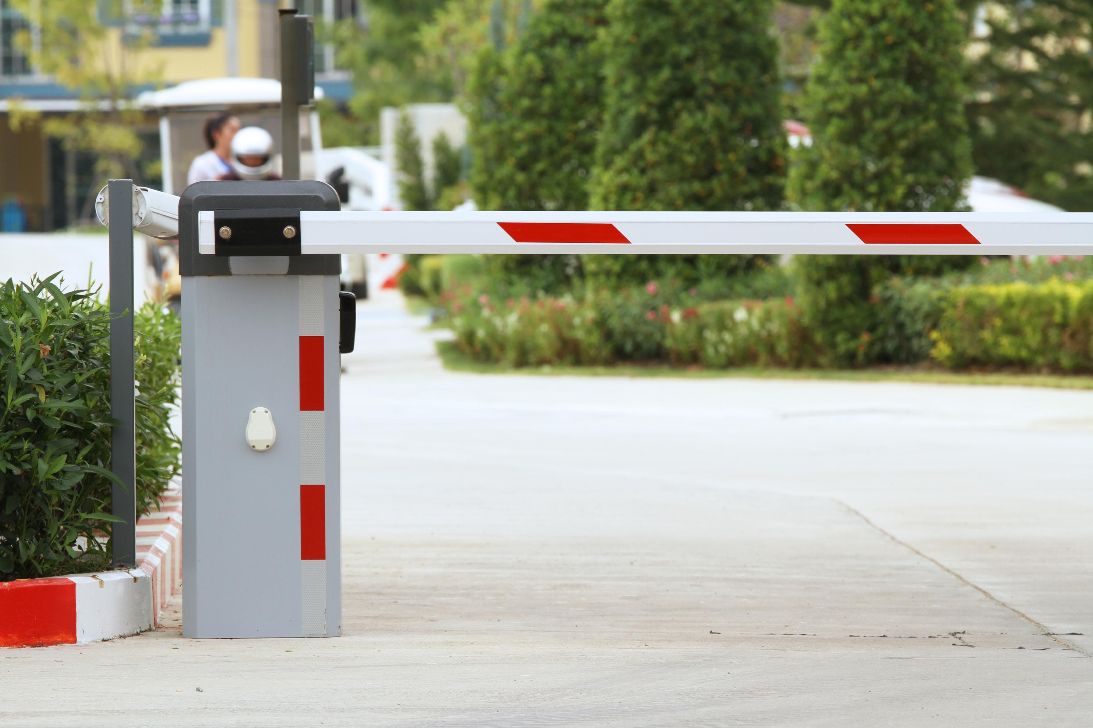
How Does a Boom Barrier Work?
What Is a Boom Barrier?
A boom barrier (also called a barrier gate, boom gate or rising-arm barrier) is the most widely deployed device for controlling vehicle movement at a defined point of entry or exit. The same machine appears on every continent and in every climate, in forms that differ far less than the sites they serve. Understanding it well means understanding two things: the operating cycle, which is essentially identical everywhere, and the specification decisions, which are not.
It is worth being precise about what the device is for. A boom barrier is a traffic control and access recording device. It is not a vehicle impact protection device. The arm is an aluminium section designed to be visible, light and (if struck) frangible. It will not arrest a vehicle driven through it, and no reputable specification suggests otherwise. That distinction shapes almost every decision later on this page, and we return to it directly when comparing barriers with bollards.
What a barrier genuinely provides is a controlled, auditable decision point in a traffic flow. Nothing passes until the system has established that it is permitted to pass, and every passage, every refusal and every manual override can be recorded against a credential, a direction, a lane and a timestamp. For most organisations that record is the real deliverable; the moving arm is simply how the decision is enforced.
How Does a Boom Barrier Work?
A boom barrier works in four stages. A sensor detects that a vehicle has arrived at the lane. An identification method authorises it, a long-range RFID tag, a recognised plate, a presented credential, a ticket, or an operator pressing a button. The controller then drives a motor and gearbox that rotate the arm to the vertical, where a limit switch or encoder halts travel. After the vehicle passes, a safety loop, photocell or safety edge confirms the lane is clear, and the controller lowers the arm and writes the event to a log.
Detect, authorise, drive, confirm, close. Everything else on this page is detail beneath those five verbs, including the specification method, which is most usefully understood as a series of questions about how hard, how often and under what conditions each of those five stages has to be performed.
Main Components of a Boom Barrier
| Component | Function | What varies between specifications |
|---|---|---|
| Barrier housing (cabinet) | Weather-resistant steel or aluminium enclosure holding the drive assembly, controller and manual release. | Material, coating system, ingress protection rating, and whether the door and seals are rated for the site's particulate and moisture exposure. |
| Drive unit | Electric motor with a gearbox (electromechanical), or a pump and cylinder (hydraulic), providing the torque that turns the arm. | Motor type (AC induction, brushless DC), gearbox form, continuous versus intermittent rating. |
| Crank and linkage | Converts the drive unit's rotation into the arm's 90-degree sweep. | Bearing specification and lubrication interval on high-cycle units. |
| Balance spring | A torsion or tension spring counterbalancing the arm's weight, so the motor moves a near-neutral load rather than lifting the full arm mass. | Spring rate must be matched to the arm actually fitted, including any skirt or articulation. |
| Boom arm | Aluminium octagonal, round or rectangular section. Options include skirt fencing, an articulated joint for restricted headroom, and integral LED illumination. | Length, section profile, mass, reflective treatment and whether the arm must be frangible at a defined point. |
| Controller / control board | The logic of the system: accepts open, close and safety inputs, drives the motor, manages timers, and communicates with upstream systems. | Number and type of inputs, safety input supervision, interface protocol, event logging and diagnostic capability. |
| Limit switches or encoder | Tell the controller when the arm has reached fully open or fully closed so the motor stops at the correct point. | Mechanical limits are simple and serviceable; encoders add continuous position and stall detection. |
| Loop detector | Electronics that sense a vehicle over a wire loop embedded in the road surface. | Channel count, sensitivity settings, frequency selection to avoid crosstalk between adjacent lanes. |
| Photocell / infrared beam | An optical beam across the lane that halts or reverses the arm if the path is obstructed. | Modulated versus unmodulated, range, and whether the signal is supervised by the controller. |
| Access control input | RFID reader, ANPR camera, ticket dispenser, push button, remote handset or intercom, the source of authorisation. | Read range, throughput, failure fallback, and whether identification must work with a closed vehicle window. |
| Manual release | A key-operated mechanism that disengages the drive so the arm can be raised by hand without power. | Key type and key control; whether release is required from outside the cabinet for emergency responders. |
| Power supply and protection | Mains input, internal supply, surge protection and, where specified, battery backup. | Supply voltage and frequency vary by region; surge and earthing provision varies with exposure. |
Drive unit and gearbox
Most barriers in commercial service are electromechanical: an AC or brushless DC motor driving a worm or helical gearbox. The gearbox converts a fast, low-torque motor output into slow, high-torque arm movement, and its self-locking characteristic helps hold the arm where it has stopped. Higher-duty models use brushless motors with electronically controlled acceleration and deceleration, which reduces mechanical shock at each end of travel. That matters more than it sounds: on a lane doing several thousand cycles a day, the shock loading at the end stops is the dominant wear mechanism, and controlling it is the main reason high-duty units last.
Hydraulic drives substitute a pump and cylinder for the motor and gearbox. They sustain continuous high-frequency operation and handle long, heavy arms more comfortably, at the expense of a fluid system that must be maintained. The selection logic between the two is covered in its own section below.
Boom arm and balance spring
The balance spring is the component most often misread. It is not a safety device; it is a counterweight. Correctly set, the arm is close to neutrally balanced throughout its travel, so the motor performs far less work and the barrier moves smoothly and quietly. Incorrectly set (most commonly after an arm has been replaced with one of a different length, mass or configuration) the motor labours, travel becomes uneven, end-stop impacts become harsher, and the drive train wears out well before its rated cycle count.
The practical rule is simple and universal: any change to the arm requires the spring to be reset. Fitting a skirt, adding an articulated joint, shortening an arm after a lane is re-marked, or substituting a heavier section all change the moment the spring has to balance. A barrier that was commissioned correctly and now moves unevenly has very often had its arm changed by someone who did not know this.
Controller and position sensing
The controller decides what happens and when. It holds the open and close timers, the logic governing which inputs may trigger movement, the response to each safety device, the fail-state behaviour on loss of power or loss of communication, and the interface to external systems. On any site where the barrier forms part of a wider security design, the controller's configuration is a specification item in its own right and should be documented rather than left to the commissioning engineer's defaults.
Position is confirmed either by mechanical limit switches at each end of travel or, on newer units, by a rotary encoder reading the drive shaft continuously. Encoders also let the controller detect that the arm has stopped where it should still be moving, which is the basis of drive-level obstruction detection.
Detection and safety devices
These are covered fully below, but the governing principle belongs here because it is the single most common specification error in the category: detection devices decide when to open; safety devices decide when it is not permitted to close. They are different device sets, with different failure consequences, and one cannot substitute for the other. A loop that reliably triggers an opening cycle may be entirely unsuitable as the device that protects a pedestrian standing under the arm.
How Does a Boom Barrier Work Step by Step?
| Step | What happens | How it works |
|---|---|---|
| 1 | Vehicle approaches and is detected | An inductive loop embedded in the road, or an infrared, radar or camera sensor, registers the vehicle's arrival at the approach point. |
| 2 | Credential is presented and read | A long-range UHF RFID tag is read at distance, a camera captures and reads the licence plate, a card or ticket is presented, or an operator issues the command. |
| 3 | Authorisation is decided | The credential is checked against the permitted list held in the controller, the access control platform or the parking system. A valid match produces an open command; an invalid one is refused and logged as a denied attempt. |
| 4 | Controller energises the drive | The control board switches power to the motor, ramping it up so the arm is not jerked off its closed stop. |
| 5 | Arm rotates to vertical | The gearbox and crank convert rotation into the arm's upward sweep, assisted by the balance spring. Travel is typically 1.5 to 6 seconds depending on arm length and duty class. |
| 6 | Open position is confirmed | A limit switch or encoder reports full open and the motor is stopped. The controller holds the arm open for the configured period. |
| 7 | Vehicle passes through | The safety loop beneath the arm and the photocell across the lane both register the vehicle occupying the passage zone. |
| 8 | Lane is confirmed clear | The controller waits until the safety loop de-energises and the photocell beam is unbroken, meaning nothing remains beneath the arm. |
| 9 | Close is triggered | Either immediately on the lane clearing, or after a configured delay, or on an exit loop being crossed, determined by how the lane has been designed. |
| 10 | Arm lowers and the event is logged | The arm returns to horizontal and stops at the closed limit. The passage (credential, direction, lane, timestamp) is written to the access control or parking database. |
At any instant during step 10 the cycle can be interrupted. If a safety device signals an obstruction while the arm is descending, the controller stops and reverses it. This reversal is the single most important behaviour in the whole cycle; a barrier whose safety devices are misaligned, dirty, disconnected or deliberately bypassed is a barrier that has lost the one function nobody can risk losing.
A second refinement worth noting at specification stage: the dwell time at step 6 is not a trivial setting. Too short and the arm begins descending while a slow or long vehicle is still clearing the lane, throwing the site onto its safety devices many times a day. Too long and throughput collapses at peak, and drivers learn to tailgate. The correct dwell is derived from the slowest expected vehicle over the measured lane length, not chosen by feel on the day of commissioning.
Electromechanical vs Hydraulic Boom Barriers
| Aspect | Electromechanical | Hydraulic |
|---|---|---|
| Drive method | Electric motor turning a gearbox and crank | Electric pump driving hydraulic fluid through a cylinder |
| Typically suited to | Parking, offices, campuses, residential entrances and the majority of commercial lanes | Long arms, sustained high cycle rates, industrial and tolling lanes |
| Arm length suitability | Shorter to medium arms | Handles longer and heavier arms more comfortably |
| Duty characteristics | Suits low to medium cycling; high-duty variants are available | Better suited to continuous, high-frequency operation |
| Behaviour in extreme ambient temperature | Motor thermal protection becomes the limiting factor at high ambient | Fluid viscosity changes with temperature; low temperatures slow movement, high temperatures thin the fluid |
| Maintenance profile | Mechanical wear points: gearbox, spring, bearings, limit switches | Fluid level, seals and hoses in addition to mechanical checks |
| Behaviour on loss of power | Manual release key disengages the drive | Manual release valve bleeds pressure to free the arm |
| Spares and servicing | Generally simpler to support with local labour | Requires fluid handling competence and correct fluid specification |
The selection is driven by arm length, cycles per hour and operating environment, not by a general belief that one technology is superior. A high-throughput industrial gate in a dusty environment and a residential entrance that cycles a hundred times a day are genuinely different engineering problems, and the honest answer is that each has a different right answer.
How to Specify a Boom Barrier for Any Site
This is the section most buyers skip and most regret skipping. Choosing a barrier is not a matter of picking from a catalogue; it is six determinations made in order, each of which constrains the next. The method below is deliberately independent of country, brand and product range, it works for any site, anywhere, and it produces a specification that can be issued to any competent supplier.
Step 1, Establish peak cycles per hour
Everything else depends on this number, and it is the number most often guessed. One cycle is one complete open-and-close. Do not use a daily total divided by working hours; that average conceals the peak that actually sizes the equipment. Instead, establish the busiest hour the lane must serve.
- Count or model the peak hour. For an existing site, count. For a new build, derive it from occupancy: the number of vehicles that must enter during the arrival peak, plus the number leaving during the departure peak, divided across the lanes provided.
- Add exits and entries separately. A lane that is bidirectional carries both.
- Allow for refusals and re-presentations. Denied credentials, failed reads and reversing vehicles all generate cycles. A 10 to 20 per cent allowance over the counted figure is a reasonable starting assumption on sites with visitor traffic.
- Identify the shift pattern. A manufacturing plant with three shift changes has three sharp peaks in a day; a shopping development has a long broad peak. The same daily total produces very different equipment requirements.
- Record the result as a number (for example, "peak 180 cycles per hour, sustained 40 minutes") because that is the figure a supplier can answer against.
Step 2, Establish lane width, and therefore arm length
Arm length follows from the clear opening the barrier must span, plus the mounting offset of the housing from the lane edge, plus a practical allowance so the arm tip does not sweep into kerbs, bollards, signage or adjacent structures.
- Measure the clear lane width at the barrier position, not elsewhere on the approach. Lanes often narrow at the control point.
- Add the offset from the housing centre to the lane edge. The housing is never on the lane line.
- Check the swept volume. The arm sweeps through a quarter-circle. Verify headroom to any canopy, soffit, pipe, cable tray or sign at the fully open position. Restricted headroom calls for an articulated or folding arm, which is heavier and changes the balance requirement.
- Understand the trade with speed. A longer arm has a greater moment of inertia, so it accelerates and decelerates more gently and takes longer to complete its travel. Arm length and opening time are not independent choices, and a specification demanding both a 6 metre arm and a 1.5 second opening is likely to be unsatisfiable.
- Consider wind loading on arms with skirts or solid infill. A skirted arm presents a significant sail area, and in exposed locations this affects both drive sizing and arm selection.
- Where a single lane exceeds the practical arm range: the correct answer is usually two barriers facing each other across the opening, not one oversized arm.
Step 3, Establish the required duty rating, with derating
A duty rating expresses how much work the barrier can do continuously without overheating or wearing prematurely. It appears on datasheets in two broad forms: a duty cycle percentage (the proportion of time the drive may be energised), or a cycles-per-hour figure, sometimes alongside an MCBF figure (mean cycles between failures) which describes expected life rather than instantaneous capability.
Two disciplines convert the peak figure from Step 1 into a defensible duty requirement:
- Do not specify at the limit. A barrier rated at exactly the site's peak will be running continuously at its ceiling during every peak, which is where thermal protection trips and service life shortens. Specify with margin above the peak, a commonly used working assumption is to select equipment rated for comfortably more than the Step 1 peak, so the lane's busiest hour sits well inside the device's capability.
- Derate for the environment. Published duty figures assume reference conditions, typically a moderate ambient temperature and clean air. A real site rarely matches them. The next major section sets out how each environmental factor erodes the catalogue figure.
The output of this step should be an explicit sentence in the specification: the required duty after derating, stated at the site's design ambient conditions. That single sentence is what separates a specification that survives a hot summer from one that does not.
Step 4, Decide the identification method
Identification should be chosen from two site facts: the size of the user population, and its rate of turnover.
| User population | Turnover | Identification approach typically suited to it |
|---|---|---|
| Small, fixed, well known | Very low | Card or remote handset credential, or attended operation. Tagging every vehicle is unnecessary overhead. |
| Large, largely stable | Low | Long-range UHF RFID for the regular population. Identification at distance, no driver interaction, high throughput. |
| Large, with constant visitor flow | Mixed | UHF RFID for the regular population plus ANPR or issued credentials for visitors, both accepted by the same controller. |
| Mostly unknown vehicles | High | Ticket or token issue with a parking platform; ANPR where plate population is consistent and a fallback exists. |
| Mixed goods and passenger traffic | Varies by class | Separate lanes or separate credentials by vehicle class, with goods traffic frequently routed through a weighbridge or dock sequence. |
| Security-sensitive, verified entry | Low to mixed | Layered identification (credential plus plate plus operator verification) with the barrier handling flow and protective equipment handling threat. |
Two cross-checks apply regardless of which row fits. First, throughput: a method that requires the driver to stop, open a window and present something adds several seconds per vehicle, which at a peak of 200 cycles per hour is the difference between a flowing lane and a queue on the public road. Second, enrolment burden: tags must be issued, recorded and revoked by someone, and a population with 30 per cent annual turnover generates a continuous administrative load that should be acknowledged in the design rather than discovered later.
Step 5, Decide the safety device set
The safety device set is determined by the traffic mix, and specifically by whether people on foot can be present in the swept zone. This is the determination with the most serious consequences and the least excuse for getting wrong.
- Vehicles only, physically segregated from pedestrians: a safety loop beneath the arm plus a photocell across the lane is the conventional minimum. The loop inhibits closing while a vehicle is present; the photocell reverses the arm if the path is obstructed during descent.
- Vehicles with occasional pedestrian presence: a loop alone is insufficient, because a loop does not reliably detect a person. The photocell becomes the primary protective device and should be positioned at a height that detects a person, not only a vehicle bumper. Consider a second beam at a different height.
- Vehicles and routine pedestrian movement in the same opening: the design is wrong. Separate the pedestrian route with its own gate or walkway. Where separation is genuinely impossible, add a safety edge on the arm, additional beams, and clear visual and audible warning of movement, and accept that the residual risk is higher than a segregated design.
- Two-wheeler and light-vehicle traffic: motorcycles and bicycles are poorly detected by loops. Where they form a meaningful share of traffic, optical or radar detection should supplement or replace loop detection for the safety function.
- Long or articulated goods vehicles: the safety loop must cover the full length of the vehicle's dwell beneath the arm, or a vehicle will be released by the detector while its trailer is still in the swept zone. Loop size and position follow the longest expected vehicle.
- In every case, the safety devices should be supervised by the controller so that a disconnected or failed device is reported rather than silently ignored. An unsupervised photocell that has failed looks exactly like an unobstructed lane.
Step 6, Establish emergency and fail-state behaviour
Every barrier has a defined behaviour on loss of power, on loss of communication with the host system, and on an emergency signal. These behaviours must be chosen from the site's life-safety strategy, not from the product default, and on many sites the choice is not the specifier's alone to make.
| Condition | Options | How to decide |
|---|---|---|
| Loss of mains power | Arm drops to closed; arm remains where it is; arm raises and holds; battery backup maintains normal operation | Determined by whether the lane is part of an evacuation route and by whether a blocked lane is acceptable. A lane that is an escape route for vehicles generally cannot be allowed to remain closed. |
| Loss of host communication | Controller falls back to local credential list; controller refuses all; controller permits all; attended operation takes over | Determined by the security posture. Refusing all is the secure choice and the one most likely to strand people; permitting all is the opposite. Local fallback lists are usually the workable middle. |
| Fire or evacuation alarm | Open and hold on a monitored contact from the alarm panel | This is almost always required where occupants or vehicles must leave. The interface should be a supervised contact, and the behaviour should be tested during drills. |
| Emergency service access | Dedicated override: key switch, radio-activated receiver, attended release, or a documented manual release procedure | Determined by the local emergency authority's expectations, which differ by jurisdiction. Establish what the responding service expects to find before the design is fixed. |
| Security lockdown | Close and hold, with defined exemptions | Must be reconciled with the evacuation behaviour above. Where lockdown and evacuation conflict, life safety takes precedence and the resolution must be written down. |
| Manual release | Key-operated drive disengagement, accessible to authorised staff and responders | Always present. Decide who holds the key, where it is kept, and how a responder gains access at three in the morning. |
Two warnings belong with this step. The terms fail-safe and fail-secure mean opposite things and are regularly used loosely in correspondence; in a specification, describe the physical behaviour in words rather than relying on the label. And the emergency behaviour of vehicle barriers is frequently subject to approval by the local fire or life-safety authority. That approval is a jurisdictional matter, and it should be established early, because discovering late that an authority expects different behaviour means rework on site.
Writing it down: a six-line specification schedule
The six determinations condense into a schedule that can be issued with a tender and answered unambiguously by any supplier. The value is in its brevity: six lines that leave no room for interpretation.
| Line | States | Example of a well-formed entry |
|---|---|---|
| 1 · Throughput | Peak cycles per hour and the duration of the peak | "180 cycles/hour sustained for 45 minutes, twice daily, bidirectional" |
| 2 · Geometry | Clear opening, housing offset, required arm length, headroom at full open | "3.6 m clear opening, 0.4 m offset, 4.5 m arm, 4.2 m headroom, articulated arm not required" |
| 3 · Duty | Required duty after derating, stated at design ambient conditions | "Rated duty to be demonstrated at 50 °C ambient and the stated particulate exposure" |
| 4 · Identification | Method per user class, with throughput and fallback | "UHF RFID for permanent population; ANPR with intercom fallback for visitors; both via the access platform" |
| 5 · Safety | Device set, mounting heights, supervision requirement | "Safety loop sized to longest vehicle, two supervised photocell beams at 0.4 m and 0.9 m, safety edge on arm" |
| 6 · Fail-state | Behaviour on power loss, communication loss and alarm; override arrangement | "Open and hold on alarm contact; battery backup for 50 cycles; local credential fallback; external key release" |
A supplier who can answer all six lines against a specific model has told you something useful. A supplier who answers only with a model name has not.
Environmental Derating: Why a Catalogue Duty Figure Is Only a Starting Point
Every duty figure on every datasheet is stated at reference conditions, a defined ambient temperature, clean air, normal humidity, a stable supply. Those conditions describe a test bench. They rarely describe a gate. Derating is the discipline of adjusting the catalogue figure to the conditions the equipment will actually experience, and it is the main reason two identical barriers in two different climates have very different service lives.
The principle is general and applies whatever the climate: identify which environmental factors are present at the site, understand the mechanism by which each one erodes performance or life, and specify accordingly. What follows is the mechanism for each of the major factors, written so that a specifier can apply it to any location.
High ambient temperature
Heat is the most direct constraint on duty cycle. An electric motor converts a proportion of its input into heat, and that heat must leave the motor and the cabinet. The rate at which it leaves depends on the difference between the component temperature and the surrounding air. As ambient rises, that difference shrinks, heat leaves more slowly, and the motor reaches its thermal limit after fewer cycles. The practical consequence is simple and often unwelcome: the number of cycles per hour a barrier can sustain falls as ambient temperature rises, and a unit comfortably within its rating in temperate conditions may trip its thermal protection repeatedly in a hot climate.
Solar gain compounds this. A dark cabinet in direct sun can sit substantially above shade air temperature, so the ambient the motor experiences is not the ambient on the weather station. Light-coloured finishes, ventilation, shading of the housing, and in severe cases forced cooling, are the usual responses. On the identification side, long periods at high temperature also shorten the life of electrolytic capacitors in control electronics and power supplies, which is a common cause of controller failures that appear unrelated to the drive.
For specification purposes: state the design ambient (the temperature the equipment must achieve its stated duty at, not the annual average) and require the supplier to confirm duty at that figure rather than at the datasheet reference.
Airborne particulates: dust, sand and industrial fallout
Fine airborne material attacks a barrier in three distinct ways, and each requires a different response.
- It abrades seals and bearings. Particulates that reach a moving interface act as a grinding medium. Shaft seals, bearing seals and linkage pivots wear faster, lubricant becomes contaminated, and clearances open up. The response is a higher ingress protection rating, sealed rather than shielded bearings, and shortened lubrication intervals.
- It fouls optical safety devices. A film of dust on a photocell lens attenuates the beam. As attenuation increases, the receiver's margin falls, and the device begins to register obstructions that are not there, or, more dangerously, approaches the point where it can no longer register obstructions that are. Nuisance reversals on a dusty site are a warning, not a nuisance. The response is cleaning frequency driven by the environment rather than the calendar, lens hoods, and supervised devices so that degradation is reported.
- It accumulates in the cabinet and insulates. A layer of dust on a motor, heatsink or control board reduces heat transfer, which interacts directly with the temperature factor above. A dusty hot site is harsher than the sum of the two factors considered separately.
Coastal and marine salt air
Within a few kilometres of a coast, and particularly where prevailing wind carries spray inland, airborne chloride is present continuously. Chloride accelerates corrosion of steel, attacks the interface between coating and substrate, and promotes galvanic corrosion wherever dissimilar metals meet, most commonly at fasteners, at the housing base, and at cable glands.
The specification response is a coating and materials system rather than a single choice: a defined corrosion protection class for the enclosure, hot-dip galvanising or equivalent on structural steel, stainless fasteners of an appropriate grade, isolation between dissimilar metals, sealed cable entries, and a washing regime. It is worth noting that stainless steel is not automatically the answer, the wrong stainless grade in a chloride environment pits readily. The grade matters more than the word.
Foundations and anchor bolts deserve particular attention in coastal conditions, because they are the hardest element to remediate once corrosion has started, and the one most often specified in plain steel by default.
Sub-zero and freeze-thaw conditions
Cold introduces failure mechanisms absent in warm climates, and they are mostly about water rather than temperature itself.
- Moisture that has condensed inside a mechanism freezes, binding linkages, limit switches and manual release mechanisms. A barrier that worked yesterday will not move today, and forcing it damages the drive.
- Lubricant viscosity rises sharply at low temperature, increasing the load on the motor at exactly the moment it has least margin. Low-temperature lubricant specification is a real requirement, not a refinement.
- Hydraulic fluid thickens, slowing movement and raising system pressure. Hydraulic units in cold climates require a fluid specified for the temperature range and frequently a heater.
- Cabinet heaters, thermostatically controlled: are the conventional response, and they bring their own requirement: a power supply sized for the heater load, which is often larger than the drive load.
- Freeze-thaw cycling damages the road surface, and with it embedded loops. Where the surface cracks and water penetrates, loop insulation degrades. Loop sealant must be specified for thermal movement, not simply for water exclusion.
- Snow and ice loading on the arm changes the balance the spring was set for, and accumulated ice on a skirted arm can be substantial.
Heavy rainfall and standing water
Water is the most common single cause of intermittent faults in barrier installations anywhere, and almost all of it is a workmanship and drainage issue rather than an equipment issue.
- Loop slots must be sealed with a sealant appropriate to the surface and the climate. A slot that admits water will eventually produce a loop with degraded insulation to earth, and the symptom is a detector that behaves erratically in wet weather and normally in dry, which is exactly the pattern that makes faults hard to find.
- Pits, draw boxes and cable chambers must drain. A pit that fills and stays full will saturate joints and glands no matter how well the components are rated. Drainage is designed, not hoped for.
- Cable entries should enter from below or be dripped, so water tracking along a cable does not run into the enclosure.
- The barrier foundation should sit above the local flood line and above the standing water level the lane experiences in heavy rain, with the surrounding surface falling away from it.
- Photocell beams are attenuated by heavy rain, so devices should have margin beyond the nominal lane width rather than being specified at the limit of their range.
Standards and Conformity: What Applies Where
This is where international readers are most often misled, usually by a supplier's marketing rather than by any deliberate deception. Requirements for powered vehicle barriers are set jurisdictionally. There is no single global standard that governs the category everywhere, and a conformity mark that is mandatory in one region carries no automatic legal status in another.
Broadly, a specifier anywhere needs to identify which of the following regimes apply in the country of installation, and then establish what each requires of this particular product in this particular application:
| Regime | What it typically governs | What the specifier must establish |
|---|---|---|
| Machinery safety | The safety of powered machinery with moving parts: risk assessment, protective device requirements, residual risk information, instructions for use | Which machinery safety regime applies in the country of installation, what it requires of a powered barrier, and what documentation the supplier must provide with the equipment. |
| Electromagnetic compatibility | That the equipment neither emits excessive interference nor malfunctions in the presence of normal interference | Which EMC regime applies, and whether the product has been assessed against it. Relevant on sites with radio systems, weighbridges or sensitive instrumentation nearby. |
| Electrical safety and installation | Supply voltage and frequency, earthing arrangement, protective devices, cable selection, isolation and labelling | The national wiring regulations, and who is competent and licensed to perform and certify the installation. |
| Radio equipment approval | UHF RFID readers, remote handsets and any other intentional radiator: permitted bands and radiated power limits | Which frequency band and power limit apply in the country, and that the supplied reader and tag variants are the ones permitted there. |
| Regional product conformity marking | Market access marking schemes, which differ by region and sometimes require in-country testing, registration or a local representative | Which marking scheme, if any, applies to this product category in this market, and what evidence the importer must hold. |
| Life safety and fire authority approval | Behaviour of barriers on escape and emergency access routes, and the interface to the alarm system | The local fire or life-safety authority's expectations for barrier behaviour on alarm and for emergency service access, established before the design is fixed. |
| Impact resistance ratings | Resistance of protective equipment to deliberate vehicle impact. Applies to crash-rated bollards and blockers, not to boom barriers | That the requirement, if present, is directed at the correct equipment. A boom barrier is not the device to which an impact rating applies. |
| Accessibility and traffic engineering | Lane widths, sightlines, queueing space, signage, markings and warning devices | The national or municipal design guidance governing the approach, which often constrains the barrier position more than the barrier itself. |
Three points follow from this table and are worth stating plainly.
- Conformity marking is not transferable between regions. A mark that permits a product to be placed on the market in one region is evidence of assessment against that region's requirements. It is not a certificate of universal suitability, and presenting it as one is a common error in international tenders.
- The obligation to identify the applicable regime sits with the specifier and the importer: not with an overseas manufacturer who may have no visibility of the destination market's requirements.
- Conformity is assessed for a product in an application. The same barrier may satisfy requirements as a vehicle-only lane device and raise additional questions where pedestrians share the opening. The application is part of the question.
Nothing on this page should be read as a statement that any particular product holds any particular approval, certification or conformity status. Approval status is a question for the supplier of the specific model, in the specific market, and should be confirmed in writing with supporting documentation before a specification is issued.
How Boom Barrier Safety Systems Work
Because the arm moves through a space that vehicles and people occupy, layered protection is the convention. Each layer works by a different physical principle, which is precisely why competent installations use more than one, a single mechanism has a single failure mode.
- Safety loop: the loop directly beneath the arm. While it senses a vehicle, the controller is inhibited from closing. This is a presence interlock: it prevents a close command being issued rather than interrupting one in progress. It does not reliably detect people.
- Photocell / infrared beam: a modulated transmitter and receiver across the lane. If the beam is broken while the arm is descending, the controller stops and reverses. This catches what a loop cannot, including pedestrians, animals and low-metal objects. Mounting height determines what it can see.
- Safety edge on the arm: a pressure-sensitive strip along the underside that signals contact. Specified where the arm could contact a person despite the other layers, typically on sites with mixed traffic.
- Obstruction detection at the drive: the controller monitors motor current or encoder feedback. A sudden rise in load, or travel that ceases when it should still be progressing, is interpreted as an impact and triggers reversal. This is a last line, not a first: it acts after contact, not before.
- Device supervision: the controller monitors that each safety device is present and responding. An unsupervised device that has failed is indistinguishable from a clear lane, which is the most dangerous failure mode in the whole system.
- Visual and audible warning: arm reflectors or integral LEDs, a flashing lamp, and on higher-risk sites a movement warning tone. Visibility of the arm at night and in poor weather is a safety function, not a cosmetic one.
- Manual release: allows the arm to be raised by hand during a power failure, so a lane never becomes permanently blocked.
- Alarm interface: a monitored contact from the fire or evacuation panel that drives barriers to open and hold, clearing egress routes. On any site with occupancy this should be treated as essential rather than optional, and tested during drills.
Technologies Used in a Boom Barrier System
A modern barrier lane brings together several distinct technologies, each with its own failure characteristics:
- Electromagnetic induction: loop detectors sensing vehicle presence through a shift in inductance.
- Passive UHF RFID: backscatter communication between a reader antenna and an unpowered tag, within nationally permitted frequency bands and power limits.
- Optical character recognition with infrared illumination: ANPR reading plates in daylight and darkness, with performance dependent on plate format and presentation.
- Motor control electronics: controlled acceleration and deceleration, current monitoring for obstruction detection, and variable-frequency drive on some models.
- Position feedback: mechanical limit switches or rotary encoders confirming arm position and enabling stall detection.
- Optoelectronic sensing: modulated infrared photocells designed to reject ambient light interference.
- Pressure-sensitive edge sensing: resistive or optical safety edges signalling contact along the arm.
- Network communication: TCP/IP, RS-485, dry-contact and in some systems OSDP interfaces to access control, parking and video platforms.
- Environmental protection engineering: ingress protection, coating systems, thermal management and surge protection, which together determine how long the rest of the list keeps working.
Where Boom Barriers Are Used
Barriers appear wherever vehicle movement must be controlled and recorded. The site types below recur in every region, and each brings a characteristic specification profile:
- Corporate campuses and office developments: staff on long-range tags, visitors on ANPR or issued credentials, with sharp arrival and departure peaks that size the duty rating.
- Logistics and distribution centres: goods vehicle movement with long vehicles, frequently sequenced with weighbridges, dock allocation and yard management, where safety loop sizing for trailer length is the critical detail.
- Manufacturing plants: shift-change peaks, contractor and goods traffic on separate credentials, and often a particulate-laden environment that drives derating.
- Ports and intermodal terminals: high cycle counts, long arms, coastal corrosion exposure and integration with terminal operating systems.
- Airports: segregated airside and landside control, staff and service vehicle management, and emergency access arrangements that are tightly specified by the operator.
- Hospitals and healthcare campuses: separation of emergency vehicle routes from general parking, priority opening for ambulances, and fail-state behaviour that must never obstruct an emergency approach.
- Universities and educational campuses: large, seasonally changing user populations with high enrolment turnover, which pushes identification toward methods that are simple to issue and revoke.
- Retail and mixed-use developments: high-turnover public parking with ticketing or plate-based tariff calculation and long broad peaks rather than sharp ones.
- Residential communities: resident vehicles on tags, visitors handled through an attended or intercom route, with quiet operation and night-time visibility mattering more than raw throughput.
- Government and institutional facilities: typically the traffic-management layer in front of protective equipment rather than the protective element itself.
- Tolling and parking operations: sustained high cycle rates paired with electronic payment or toll collection, where duty rating and MCBF dominate the selection.
TimeWatch supplies boom barriers and related parking and traffic control equipment internationally, and maintains dedicated regional sites for several markets, see the regional guidance below for where to look for locally relevant information.
Integration With Other Systems
A barrier rarely operates alone. The integrations below recur across site types:
- Access control: the credential database that governs doors and turnstiles also governs the vehicle lane, so a single revocation closes every route at once.
- Parking management software: occupancy counting, space allocation, tariff calculation and reporting by period, tenant or vehicle class.
- ANPR and long-range readers: identification without driver interaction, which is the main lever on lane throughput.
- Visitor management: a pre-registered visitor's vehicle recognised at the gate, with arrival notified to the host and the visit recorded.
- Video surveillance and analytics: camera footage bookmarked against each barrier event, so any passage can be retrieved from its log entry rather than by scrubbing recordings.
- Fire and evacuation systems: automatic open-and-hold on a monitored alarm contact.
- Weighbridges and dock systems: in industrial and logistics settings, release conditional on the weighment or the dock assignment being complete.
- Building and estate management platforms: barrier status, fault and cycle-count data surfaced alongside other plant for maintenance planning.
- Intercom and attended control: a human decision path for exceptions, which every site eventually needs.
Installation Considerations
Most barrier problems trace back to installation rather than equipment selection. The principal considerations are consistent worldwide:
- Foundation: a level concrete plinth with correctly positioned anchor bolts, sized for the unit and the ground conditions. An out-of-level housing produces uneven travel and premature wear, and cannot be corrected by adjustment.
- Position relative to the approach: the barrier must sit where a stopped vehicle does not block the public road, with adequate queueing space ahead of it and adequate sightlines for the driver.
- Loop cutting: slot depth and width to specification, the correct number of turns, and the slot sealed so water cannot enter. Loop faults are among the most frequent causes of erratic behaviour and almost all are workmanship issues.
- Loop positioning and sizing: arming, safety and exit loops each positioned for the lane geometry and sized for the longest expected vehicle.
- Detector frequency separation: adjacent lanes must have their detectors set to different frequencies to prevent crosstalk.
- Cable routing and separation: loop feeder cables twisted and routed away from power cabling to limit induced interference.
- Earthing and surge protection: outdoor electronics on long cable runs are exposed to induced surges. Proper earthing and surge arrestors materially affect reliability, particularly in regions with high lightning incidence.
- Arm length, swept volume and headroom: verified on site at the fully open position, not assumed from the drawing.
- Power supply: correct voltage and frequency for the region, stable supply, and battery backup where the lane must keep operating through outages.
- Camera geometry for ANPR: mounting height, angle, stand-off and illumination set during design. Recognition performance is largely determined before the camera is ever powered.
- Drainage: surfaces falling away from the housing, pits and draw boxes drained, cable entries protected against tracking water.
- Commissioning record: configured timers, safety device positions, spring setting and fail-state behaviour recorded in writing and handed over, so the next engineer is not guessing.
Maintenance Considerations
Barriers are mechanical devices working outdoors and cycling continuously. Routine attention is what separates a unit that reaches its rated life from one that does not. Intervals should be driven by cycle count and environment rather than by the calendar alone:
- Inspect and lubricate the drive mechanism, linkage and bearings at the manufacturer's interval, shortened where particulates are present.
- Check balance spring tension, and always reset it after any change to the arm.
- Verify limit switch or encoder positions so the arm stops cleanly at both ends without impacting the stops.
- Clean photocell lenses and confirm alignment. Dust films, insect nests and spider webs are among the most frequent causes of false obstruction detection anywhere in the world.
- Test loop continuity and insulation resistance to earth, particularly after any road resurfacing or ground works.
- Inspect enclosure seals, gaskets and cable glands, and check that drainage paths remain clear.
- Inspect coatings for corrosion onset, especially at fasteners and the housing base in coastal environments.
- Confirm the manual release operates, before it is needed, not during the incident.
- Test the alarm interface as part of scheduled evacuation drills, and record the result.
- Inspect the arm for impact damage and confirm reflective strips or LEDs remain visible at night.
- Review the controller's cycle counter and fault log against the design assumptions. A lane cycling well above its design peak is a lane that needs either a second lane or a higher-duty unit.
Benefits and Limitations
Benefits
- Controlled, recorded vehicle access without permanent manual staffing at the point of entry.
- High throughput, fast opening on suitable models keeps queues moving at busy gates and off the public road.
- A complete audit trail of entries, exits, refusals and overrides by credential, direction, lane and time.
- Integrates with access control, parking, video and visitor systems, so vehicle and pedestrian movement share one record.
- Deters casual unauthorised entry and enforces allocation of parking capacity.
- A mature, widely supported technology with a deep supply base, so spares and competent labour are generally obtainable in most regions.
Limitations and considerations
- It is not a protective barrier. A boom arm will not stop a vehicle driven through it deliberately. Where hostile vehicle mitigation is the requirement, crash-rated bollards or road blockers are the correct equipment, with the boom barrier handling routine traffic in front of them.
- Tailgating is possible: a second vehicle can follow closely before the arm descends. Sites requiring strict one-vehicle-per-authorisation control pair the barrier with loop-based sequence logic, a second barrier forming an interlocked airlock, or video verification.
- ANPR accuracy varies with plate format, condition, weather, lighting and vehicle speed, and requires a fallback path.
- Loop detectors are embedded in the road surface, so resurfacing, heavy vehicle damage, ground movement and water ingress can disturb them, and repair means cutting the surface again.
- Duty rating must match the site after derating. A unit specified for light use will fail early in a high-throughput lane, and a unit specified at reference conditions may fall short in a hot or dusty one.
- Arm length and opening speed trade against each other. Wide lanes and very fast cycles are competing requirements, and a specification that demands both may need two barriers rather than one.
- Jurisdictional requirements vary: so an arrangement that is routine in one country may require different behaviour, documentation or approval in another.
Exact behaviour (opening time, safety response, integration options, duty rating and environmental limits) depends on the specific model, controller, firmware and site configuration. Figures should always be confirmed against the datasheet for the equipment actually being specified, at the actual design conditions.
Boom Barrier vs Bollard: What Is the Difference?
| Boom barrier | Security bollard | |
|---|---|---|
| Primary purpose | Traffic control and access recording | Physical vehicle impact resistance |
| Resists a deliberate vehicle impact | No | Yes, where crash-rated to a recognised impact standard |
| Typical cycle speed | Fast, typically suited to high-volume lanes | Slower for hydraulic rising types; fixed types do not move |
| Lane coverage | Spans the full opening with one arm | Multiple units set across the opening at defined spacing |
| Visual signal to the driver | Clear and unambiguous, an arm across the lane | Less conspicuous when lowered; requires its own signalling |
| Common pairing | Handles routine traffic flow | Sits behind or alongside the barrier to provide the protective line |
The two are complements, not alternatives. Sites with a genuine hostile-vehicle requirement routinely install both: the barrier manages everyday flow and records it, the bollards provide the protective line. Specifying one where the other is required is the most consequential error in this product category, and it is usually made at the briefing stage rather than by the engineer.
Regional Guidance: India, Saudi Arabia and the UAE
This page is written to be useful anywhere, which means it deliberately avoids national specifics: local availability, local supply and installation arrangements, local regulatory expectations and local climate guidance all differ, and generic advice on those subjects is worth less than none.
For three markets, TimeWatch maintains dedicated regional sites with locally relevant versions of this guidance, local product availability and local support arrangements. If you are specifying in one of them, start there rather than here:
- India: timewatchindia.com, How does a boom barrier work?
- Saudi Arabia: timewatcharabia.com, How does a boom barrier work?
- United Arab Emirates: timewatchuae.com, How does a boom barrier work?
Readers elsewhere are in the right place. The specification method, derating principles and conformity framework on this page are written to be applied to any location, what you supply is the local design conditions and the applicable jurisdictional requirements, and the method does the rest.
Frequently Asked Questions
How does a boom barrier work?
A boom barrier works in four stages. A sensor detects that a vehicle has arrived, an identification method authorises it, the controller drives a motor and gearbox that rotate the arm to vertical, and a safety device confirms the lane is clear before the arm is lowered again. Each passage is recorded with the credential, direction, lane and timestamp.
How do I work out the duty rating a boom barrier needs?
Start from the peak hour rather than the daily total, because the peak is what sizes the equipment. Count or model the busiest hour the lane must serve, count entries and exits separately, add an allowance for refused credentials and re-presentations, then specify equipment rated comfortably above that figure rather than exactly at it. Finally, derate the catalogue figure for the site's ambient temperature and air quality, because published duty ratings assume reference conditions.
What arm length should I specify for my lane?
Arm length is the clear opening at the barrier position, plus the offset from the housing centre to the lane edge, plus a practical allowance so the arm tip clears kerbs, bollards and signage. Measure the clear width at the barrier itself, because lanes frequently narrow at the control point. Remember that a longer arm has greater inertia and therefore takes longer to travel, so arm length and opening time cannot be specified independently of each other.
Does ambient temperature affect how many cycles a barrier can perform?
Yes. A motor must shed the heat it generates, and the rate at which heat leaves depends on the difference between component temperature and surrounding air. As ambient temperature rises that difference shrinks, heat leaves more slowly, and the barrier reaches its thermal limit after fewer cycles. Solar gain on the housing makes this worse, so the ambient the motor experiences can be well above the shade air temperature.
Which standards and approvals apply to a boom barrier?
It depends entirely on the country of installation. Requirements for powered vehicle barriers are set jurisdictionally and typically span machinery safety, electromagnetic compatibility, electrical installation rules, radio approval for any readers or handsets, regional market conformity marking, and local life-safety approval of emergency behaviour. A conformity mark required in one region is not automatically accepted in another, so the specifier should identify which regime applies locally and confirm the status of the specific model in writing with the supplier.
How does a boom barrier detect a vehicle?
Most barriers use an inductive loop embedded in the road surface. The loop carries an alternating current, and when a vehicle's conductive mass enters its field the loop's inductance changes and the detector registers a presence. Because a loop senses conductive mass rather than presence in general, it may not reliably detect pedestrians, bicycles or motorcycles, which matters when choosing devices for the safety function rather than the opening function.
How long does a boom barrier take to open?
Typically between 1.5 and 6 seconds, depending on arm length, drive type and duty class. Shorter arms on high-speed units open fastest, while long or skirted arms and heavy-duty industrial barriers take longer. The exact figure is a specification of the individual model and should be confirmed against its datasheet.
Can a boom barrier stop a vehicle?
No. A boom barrier is a traffic control and access recording device, not an impact-resistant barrier. Its arm is designed to be light and visible, and it will break if a vehicle is driven through it. Where physically resisting a vehicle is the requirement, crash-rated bollards or road blockers are the appropriate equipment, usually installed alongside a barrier that handles routine traffic.
Should a boom barrier fail open or fail closed during a power failure?
That is decided by the site's life-safety strategy rather than by the product default. A lane forming part of a vehicle evacuation route generally cannot be allowed to remain closed, while a lane protecting a secure area may be required to hold closed. Every barrier also includes a manual release that disengages the drive so the arm can be raised by hand, and the specification should state who holds the key and how an emergency responder gains access. In many jurisdictions the emergency behaviour of vehicle barriers is subject to approval by the local fire or life-safety authority, so establish that expectation before the design is fixed.
What is the difference between an electromechanical and a hydraulic boom barrier?
An electromechanical barrier uses an electric motor and gearbox to move the arm, while a hydraulic barrier uses a pump and cylinder. Electromechanical units suit most commercial and parking applications and are generally simpler to support with local labour. Hydraulic units are usually selected for longer arms, heavier duty and sustained high cycle rates, and they add fluid, seal and hose maintenance to the routine, with fluid viscosity varying across the temperature range.
TimeWatch has several websites, which one should I use?
This site is the international reference and serves readers outside the three markets that have their own regional sites. If you are specifying in India, Saudi Arabia or the United Arab Emirates, use the regional site for that market, because it carries locally relevant guidance, local availability and local support arrangements that a market-neutral page cannot provide. Readers elsewhere should use this site, applying the specification method here to their own design conditions and local regulatory requirements.
