
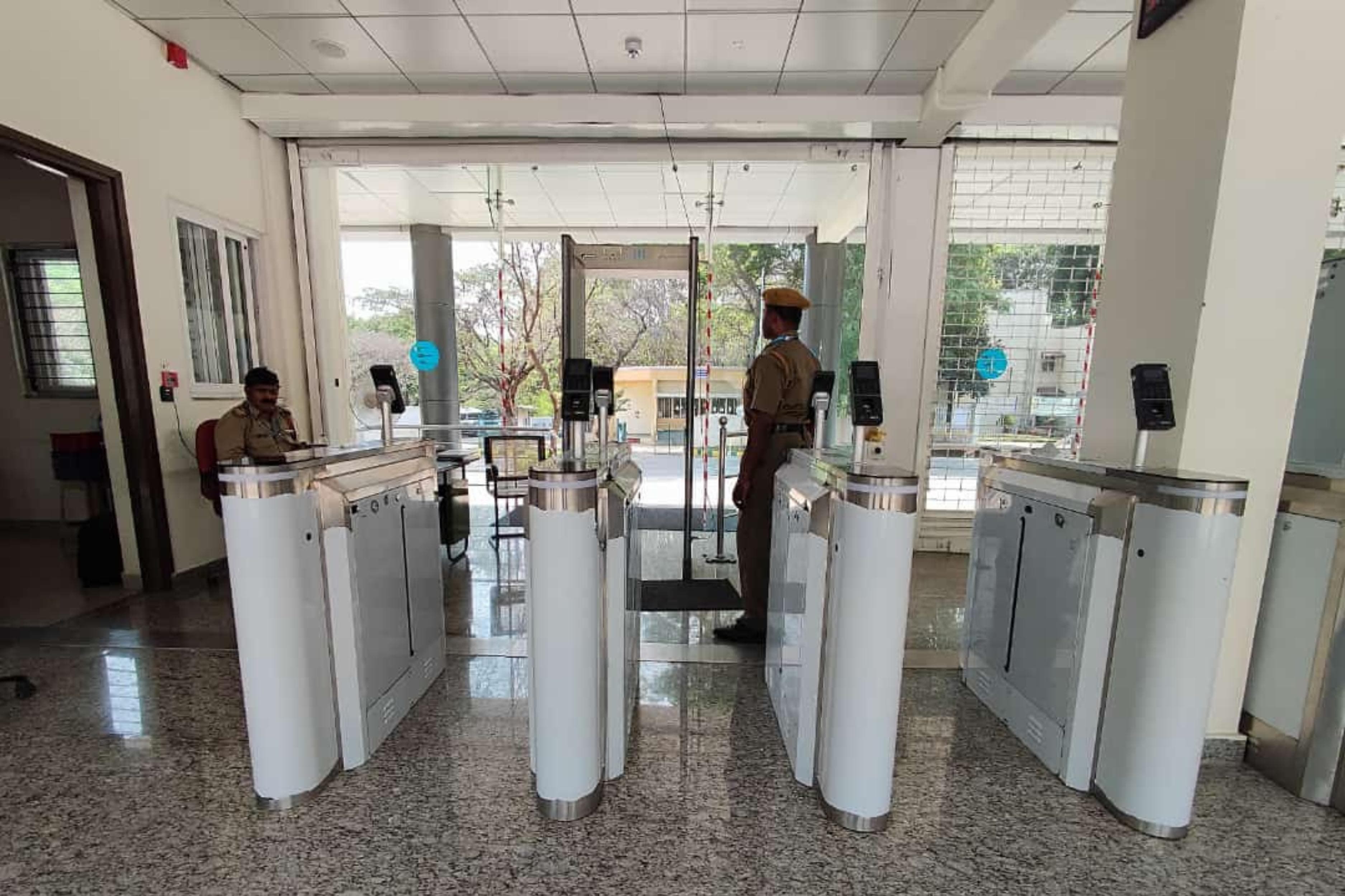
How Does a Swing Barrier Work?
What Is a Swing Barrier?
It is also called a swing gate or a swing turnstile, and all three names describe the same device. It belongs to the same family as the flap barrier and the tripod turnstile, and in a real entrance the three are frequently installed side by side. The difference between them is purely mechanical, but that mechanical difference decides which lane a given person is physically able to use, which makes it a design decision rather than a procurement preference.
The honest framing is that a swing barrier is a controlled decision point, not a physical defence. Panels on most models are waist or chest height and can be climbed or vaulted by anyone determined to do so. What the device actually delivers is that nobody passes without being identified, every passage is recorded, and anything irregular raises an alarm that someone is responsible for answering.
Most of this page is about the second question that follows from that: given a mechanism that works identically everywhere, how do you decide how many lanes to install, how wide they should be, how many infrared beams they need and what they should do when the fire alarm sounds? Those answers are site-specific, and they are what separates an entrance that works from one that has to be rebuilt.
How Does a Swing Barrier Work?
A swing barrier works in five stages. A person presents a credential at the reader built into the pedestal head. The controller validates it against the permitted list. On a valid result the drive motor rotates the swing panel roughly 90 degrees about its vertical axis, clearing the lane. The infrared array tracks the passage, counting bodies and reading direction as beams break and restore in sequence. Once passage is confirmed complete the panel closes and the event is written to the log.
Present, validate, rotate, track, close. Everything else on this page is detail beneath those five verbs, and the specification method further down is most usefully understood as a series of questions about how many lanes of this kind you need, how wide each should be, and what the third and fifth verbs should do under pressure.
Main Components of a Swing Barrier
| Component | Function | What varies between specifications |
|---|---|---|
| Pedestal housings | Enclosures standing either side of the lane, holding the drive assembly, controller, sensor array and reader. Usually stainless steel or powder-coated steel, with the profile matched to the architecture around them. | Length and internal layout, which govern how many beam pairs fit and how far apart they sit; material grade, which matters where humidity or airborne salt is a factor. |
| Swing panel and panel mount | The moving element (toughened glass, acrylic or steel) fixed to a mounting boss on the drive shaft. Panel height and width define the lane geometry and the effort required to climb or duck. | Material and therefore mass, panel height, and whether the mount allows field adjustment of the closed position. |
| Drive motor and gearbox | Typically a brushless DC servo motor with a reduction gearbox, supplying the torque that rotates the panel and the controlled deceleration that stops it cleanly at each end of travel. | Torque rating and duty rating, both of which must suit the panel mass and the site's expected cycle count rather than a nominal figure. |
| Position feedback encoder | Reports shaft position continuously, so the controller always knows the panel's angle and can detect an obstruction by monitoring drive load against expected position. | Resolution, and whether obstruction sensitivity is exposed as a configurable parameter or fixed in firmware. |
| Main controller | The logic of the lane. Accepts credential and sensor inputs, drives the motor, runs the passage timers and anti-tailgating logic, and communicates with the access control platform. | Where the access decision is actually taken, how many alarm conditions are distinguished, and how the lane behaves if the network link drops. |
| Infrared sensor array | Transmitter and receiver beam pairs at multiple heights along both pedestals, tracking objects and people through the lane. | Beam pair count, vertical distribution and spacing along the lane. This is the specification that decides anti-tailgating quality and the one most often left unstated. |
| Credential reader | Card, face, fingerprint, QR or mobile reader mounted in or on the pedestal head, facing the approach direction. | Reader technology, mounting height and angle, and whether more than one method can be accepted on the same lane. |
| Direction indicators | Arrow or cross indicators on the pedestal head telling the user whether the lane is open to them and in which direction. | Visibility from the approach distance, and whether indication is pictographic rather than text-based, which matters wherever the user population does not share one language. |
| Alarm | Audible and visual annunciation for tailgating, wrong-direction entry, forced passage or a panel held open beyond its timer. | Whether violation types are distinguished in the alarm and in the log, and whether tone and volume can be set for the acoustic environment. |
| Manual release | A mechanism that disengages the drive so the panel can be pushed open by hand during a power failure or an evacuation. | Whether release is automatic on power loss or requires a deliberate action, and whether operation of the release is itself signalled. |
| Power supply | Regulated low-voltage supply for drive and electronics, commonly with battery or UPS provision where the lane must keep functioning through an interruption. | Input voltage and frequency vary by region; backup duration and whether it is supplied as standard vary by model and by how the site is specified. |
Pedestals and the swing panel
The pedestal is not merely a cover. Its length and internal layout determine how many sensor beams can be fitted and how far apart they sit, which in turn determines how well the lane can distinguish one body from two. A short pedestal is a shorter sensing baseline, and no amount of processing recovers information the optics never collected.
Panel material is the other decision taken at this stage, and it is mechanical as much as aesthetic. A toughened glass panel carries considerably more rotational inertia than an acrylic one, and it must be matched to a drive rated for that mass at the site's expected cycle count. A heavy glass panel on an undersized drive degrades predictably: the motor runs hot, the gearbox wears, and travel becomes progressively less crisp until someone diagnoses it as a controller fault.
Drive motor, gearbox and position feedback
Most current swing barriers use a brushless DC servo motor with a reduction gearbox. Brushless construction removes the brush wear that otherwise limits cycle life in a lane performing thousands of movements a day, and the servo arrangement gives the controller fine control over acceleration and deceleration, so the panel starts and stops smoothly rather than snatching at either end.
The encoder on the shaft closes the loop. Because the controller knows the panel's angle at every instant, it can stop the panel mid-travel if something is in its path, hold it open on command, and report a mechanical fault rather than simply stalling. Obstruction detection works by monitoring drive load against expected position: a load rising where none should be is read as contact, and the panel halts or reverses according to configuration. That is the primary safety behaviour of the device and it is worth testing deliberately at commissioning rather than assuming.
Controller and credential reader
The controller holds the passage timers, the direction rules for the lane, the response to each alarm condition and the interface to the access control platform. The reader is mounted in the pedestal head so the user presents a card or a face without breaking stride.
Where the validation decision is actually taken (in the reader, in a local access control panel, or in server-side software) varies by system design and determines how the lane behaves when the network link drops. A lane that fails closed on a network outage and a lane that falls back to a locally cached list behave very differently at nine in the morning, and that is a point to settle during design rather than discover during commissioning.
The infrared sensor array
This is the subsystem that determines how good the barrier actually is, and it is the component least often interrogated during specification. It has its own section immediately below.
How Does a Swing Barrier Work Step by Step?
| Step | What happens | How it works |
|---|---|---|
| 1 | A person approaches the lane | The array registers a body at the approach side and the direction indicators show the lane's current state. Clear indication at approach distance is what prevents people queueing at a lane set against them. |
| 2 | A credential is presented | A card is tapped, a face is presented to the terminal, a finger is placed on the sensor, or a QR code is shown to the scanner in the pedestal head. |
| 3 | Authorisation is decided | The credential is checked against the permitted list held in the controller, the access panel or server software, along with any time, direction or anti-passback rule. A valid match produces an open command; an invalid one is logged as a denied attempt. |
| 4 | The controller commands the drive | The control board energises the servo motor with a ramped acceleration profile, so the panel does not snatch at the start of travel. |
| 5 | The panel rotates about its vertical axis | The gearbox turns the panel through roughly 90 degrees, swinging it clear of the lane. The encoder confirms the fully open position and the drive holds it there. |
| 6 | The person enters the lane | Beams in the entry zone break in sequence. The controller begins counting bodies and establishing direction of travel. |
| 7 | Passage is tracked | As the person moves along the lane, successive beam pairs break and restore. The order and the heights involved tell the controller how many bodies are present and which way they are moving. |
| 8 | Passage is confirmed complete | When the exit-side beams have cleared and no body remains in the lane, the controller treats the authorised passage as finished. |
| 9 | The panel rotates closed | The drive returns the panel to the closed position, decelerating into the stop. If a beam breaks during closing, the panel halts or reopens according to configuration. |
| 10 | The event is logged | The passage (credential, direction, lane, timestamp and any alarm raised) is written to the access control or attendance database. |
If the array detects a second body following on one authorisation at step 7, the controller raises a tailgating alarm and, depending on configuration, closes the panel against the follower or holds the lane locked pending an operator reset. That behaviour is the subject of the next section, and it is the single thing most worth testing before an entrance is accepted.
How the Infrared Array Detects Tailgating
The array is a set of infrared transmitter and receiver pairs facing each other across the lane, mounted at several heights along the length of both pedestals. Each pair forms a beam. When something interrupts a beam, the receiver stops seeing its transmitter and the controller registers that beam as broken. On its own, that is a presence detector and nothing more.
What makes it useful is the sequence. Because the beams sit at known positions along the lane and at known heights, the order in which they break and restore describes a movement rather than a presence. A single adult walking through produces a smooth front-to-back progression. Two adults walking close together produce a different signature: beams at the rear of the lane remain broken after the front beams have restored, and the controller reads that as two bodies on one authorisation. Walking in from the wrong end reverses the sequence, which is how wrong-direction entry is caught. A low break with nothing above it is probably a bag or a trolley; a break that stops mid-lane is probably someone who turned back.
From that, the controller derives three outputs continuously: direction of travel, body count within the lane, and anomaly classification for anything that fits neither pattern. Each is written to the log with its own classification so it can be reviewed later against video.
Which leads to the most important point anyone can make about specifying swing barriers: the sensor array, not the panel, determines how good the anti-tailgating is. Beam count, beam spacing and beam height distribution decide whether the lane can distinguish an adult carrying a child from two adults walking close together, a genuinely difficult discrimination that requires beams low enough to see legs and enough of them along the lane to separate one gait from two. A lane fitted with too few beams, or with all of them clustered at one height, cannot resolve a close follower at all: the two bodies read as one continuous interruption and nothing is flagged. No quality of panel, finish or drive compensates for that. When comparing equipment, the number and arrangement of beam pairs is the specification to interrogate first, and it is the one most often absent from a datasheet summary.
Exactly how a controller responds to a detected violation varies by model and configuration. Common options include an audible alarm only, an alarm plus a message to the security desk, closing the panel against the follower, and holding the lane locked until an operator resets it. Which of those is appropriate is a site decision tied to whether anyone is actually present to respond.
Why the Swing Barrier Is the Accessible Lane Type
This is the swing barrier's defining characteristic and the reason it exists alongside faster lane types rather than being replaced by them. Because the panel rotates about a vertical axis at the pedestal and swings clear of the opening, the lane can be made considerably wider than other lane types allow. A wide swing lane takes a wheelchair, a trolley, a suitcase, a delivery, a pram or a person walking with assistance. A tripod turnstile physically cannot: its rotating arms define a fixed, narrow aperture that no configuration widens.
That is why most real installations pair several standard lanes with at least one wide swing lane. The standard lanes carry the bulk of the flow at peak; the wide lane carries everybody the standard lanes exclude, which is a larger and more varied group than most briefs assume. It includes wheelchair users, but also anyone with luggage, anyone pushing equipment, anyone with a service animal, and the contractor with a toolbox who would otherwise find a propped-open fire door.
The practical consequence is worth stating directly: the wide accessible lane is a requirement, not an upgrade. Specifying an entrance entirely from standard lanes creates an access problem on day one, and the field solution to that problem is almost always a door propped open beside the lane bank, which defeats the entrance control entirely and does so invisibly, since no log entry records it. Getting the lane mix right at design stage is far simpler than retrofitting a wide lane into a finished floor with services already cast in, and it is one of the few entrance decisions that is effectively irreversible once the floor is laid.
Fail-Safe and Fail-Secure: Deciding Emergency Behaviour
On a fire alarm signal or a loss of power, swing barrier panels are commonly configured to open and hold, clearing the egress route so the lane cannot obstruct evacuation. This is the fail-safe configuration, and it is the usual choice on any lane forming part of a designated escape route.
The alternative is fail-secure: panels remain locked in the closed position on power loss, so the boundary cannot be opened simply by cutting the supply. Both behaviours are configurable in the controller and both are legitimate, for different routes within the same building.
The practitioner point here is a governance one rather than a technical one. Fail-safe versus fail-secure must be decided with the building's life-safety strategy, not selected by whoever commissions the controller and certainly not left at a factory default. The decision belongs to whoever owns life safety for that route, taken in consultation with the security requirement, and it should be documented before commissioning and tested as part of acceptance. Where a lane is deliberately fail-secure, the escape provision has to come from somewhere else (an adjacent door, a break-glass release) and that provision belongs in the same conversation and the same drawing. The manual release inside the pedestal complements this decision; it does not substitute for it, because it depends on someone being present and knowing it exists.
How to Specify an Entrance Line for Any Site
This is the section most entrance projects skip, and skipping it is why so many lobbies end up with the wrong number of lanes, no accessible provision, an array too sparse to detect what it was bought to detect, and a fail-state nobody chose. Specifying an entrance line is not a matter of counting people and picking a product. It is six determinations made in order, each constraining the next, and the first three are about the building and its users rather than about the equipment.
The method below is deliberately independent of country, brand and product range. It works for any site anywhere and produces a specification that can be issued to any competent supplier and answered unambiguously.
Step 1, Derive the peak arrival rate, not the headcount
The first number is people per minute at the busiest moment in the busiest direction, not people per day. An average conceals the peak, and the peak is the only thing that determines whether the entrance works.
- Count at an existing entrance during its real peak, in both directions, on an ordinary day rather than a quiet one. Fifteen minutes of observation produces a better number than any assumption.
- For a new building, derive the peak from occupancy and arrival pattern. A facility where most occupants arrive within a twenty-minute window has a completely different requirement from one with a flat arrival curve at the same daily total.
- Identify the shape of the peak, not only its height: a sharp shift-change spike and a broad commuter arrival need different lane counts even at the same maximum.
- Count both directions separately. Many entrances are heavily asymmetric in the morning and reverse in the evening, which bears on how many lanes are set in each direction and whether any are bidirectional.
- Record the result as a number with a duration (for example "peak 110 persons per minute inbound, sustained 15 minutes, weekday mornings") because that is a figure a supplier and a designer can both answer against.
Step 2, Derive the lane count from the peak
Lane count follows arithmetically from the peak once the realistic per-lane rate is established, and the realistic rate is always below the catalogue rate.
- Start from the mechanism's cycle, then deduct. A swing panel must complete its rotation in both directions and the array must confirm passage before the next authorisation, so the lane's own cycle sets a ceiling.
- Deduct for credential presentation time: which is usually the real constraint. A lane whose mechanism supports a high rate delivers far fewer passages if each person needs several seconds to find a card.
- Deduct for violations and resets. Every tailgating alarm that locks a lane consumes the throughput of the people behind it, so a site expecting a high violation rate needs either more lanes or a less disruptive alarm response.
- Add a lane for failure and maintenance. A bank sized exactly to the peak has no capacity the day one lane is out of service, and lanes do go out of service.
- Treat any throughput figure as approximate and equipment-dependent: including your own derived figure, and state it that way in the specification so it is not read as an assured behaviour.
Step 3, Set the ratio of standard to accessible wide lanes
This is the determination most often made by default, and the one most expensive to reverse. It is set by the expected user mix, not by a rule of thumb.
- Characterise the user population honestly: wheelchair users, people with assistance animals or walking aids, people with luggage or prams, contractors with equipment, staff moving trolleys, delivery traffic routed through the main entrance.
- Estimate the proportion of passages that cannot use a standard lane: and remember it is passages rather than people: one person moving equipment twenty times a day generates twenty wide-lane passages.
- Provide at least one wide lane in any bank: and more where the proportion justifies it or where a single wide lane would become a queue of its own at peak.
- Place the wide lane where it does not read as a side entrance. An accessible lane positioned at the far end of a bank, behind a planter, is technically present and practically a problem.
- Confirm the local accessibility requirement before fixing the layout, because minimum clear widths and provision rules are set jurisdictionally and are not interchangeable between countries. See the section that follows.
Step 4, Specify the infrared array from the anti-tailgating behaviour required
Having established how many lanes and of what width, specify what the lanes must actually be able to detect. This is the step that separates a specification from a shopping list.
- State the discrimination required in behavioural terms (for example, "must distinguish an adult accompanied by a child from two adults walking in close succession") rather than naming a feature.
- Specify a minimum number of independently processed beam pairs and require a stated vertical distribution, because beams clustered at one height cannot resolve a close follower however many there are.
- Require the beam layout to be disclosed: as a drawing or a schedule of positions, rather than accepting a single summary figure. Two products quoting the same beam count can behave very differently.
- Specify how violations are to be classified and logged: distinguishing tailgating from wrong-direction entry from forced passage, since an undifferentiated alarm is of limited use in review.
- Specify the response to a violation (alarm only, alarm plus notification, panel closure, lane lockout) chosen against whether anyone is present to respond, and require it to be demonstrated at acceptance.
Step 5, Establish fail-safe or fail-secure from the life-safety strategy
The fail state is a life-safety determination that happens to be implemented in a controller setting. It is derived from the building, never from the product default.
- Identify which lanes form part of a designated escape route, from the building's fire strategy rather than from the floor plan's appearance.
- Set fail-safe on those lanes and record the decision, its owner and the date, so that a later controller replacement does not silently revert it.
- Where a lane is deliberately fail-secure: name the alternative escape provision explicitly (the adjacent door, the break-glass release) and show it on the same drawing.
- Require the fire panel interface to be wired and tested at commissioning: not added afterwards, and require the test to be repeated at scheduled drills.
- Confirm the local requirement, since fire-egress rules governing how barriers behave on alarm differ between jurisdictions and are commonly enforced by an authority with its own approval process.
Step 6, Match panel material, drive duty and credential method to each other
The last step is internal consistency. Three choices that are usually made separately have to agree, and a mismatch between them is the commonest cause of premature wear.
- Match the drive rating to the panel mass and the cycle count together. A heavy glass panel at a high daily cycle count is a different duty from the same panel at a low one, and the rating must be stated against both.
- Derate for the environment the lane will actually see. A catalogue duty rating assumes reference conditions: high ambient reduces permissible duty and stresses electronics, airborne particulates abrade seals and settle on the array's optics causing false readings, salt-laden coastal air drives the corrosion specification for pedestals and fixings, sub-zero exposure may require heaters, and heavy rainfall at a semi-open entrance demands sealing and drainage attention. State the conditions and require the supplier to confirm suitability for them.
- Choose the credential method against presentation time: because that is what sets the real lane rate. A contactless method that works at walking approach outperforms one requiring a deliberate stop, regardless of lane mechanics.
- Specify reader mounting height and angle: since a reader people have to search for slows every single passage and the effect compounds across the peak.
- Identify which conformity and electrical regimes apply locally: machinery safety, electromagnetic compatibility, regional product conformity marking and national wiring rules all differ by jurisdiction, and a mark required in one region is not automatically accepted in another. Establish which regime applies before selecting equipment, and make no assumption that a product carrying one marking satisfies another.
Writing it down: a six-line entrance schedule
The six determinations condense into a schedule short enough to issue with a tender and specific enough that a bare model name cannot pass as an answer.
- 1Peak demand: persons per minute at peak, by direction, with the duration of the peak and how it was derived. Example of a well-formed entry: "Peak 110 persons/minute inbound sustained 15 minutes on weekday mornings, counted at the existing entrance; evening outbound peak 70/minute over 30 minutes."
- 2Lane count and configuration: total lanes, direction setting of each, the per-lane rate assumed and the deductions applied, plus the spare lane allowed for failure and maintenance.
- 3Accessible provision: number of wide lanes, clear width required, their position within the bank, the proportion of passages they are sized for, and the local accessibility requirement they were set against.
- 4Detection requirement: the discrimination required stated behaviourally, the minimum independently processed beam pairs with required vertical distribution, the beam layout to be disclosed, violation classification, and the response to each violation type.
- 5Emergency behaviour: fail state per lane, derived from the fire strategy, with the alternative escape provision named for any fail-secure lane and the fire interface test included in acceptance.
- 6Equipment consistency: panel material and mass, drive duty rating stated against both mass and cycle count, environmental derating for the conditions actually expected, credential method chosen against presentation time, and the conformity and electrical regimes identified for the country of installation.
A supplier who can answer all six lines against a specific model has told you something useful. A supplier who answers with a lane width and a cycle time has not.
Accessibility and Egress Requirements Differ by Jurisdiction
Two of the six determinations above (accessible lane provision and emergency behaviour) are not purely engineering choices. Both are governed by rules that are set nationally or regionally and that differ in substance rather than only in wording. Establish both before the lane layout is fixed, because both have consequences that are cast into the floor.
On accessibility, the questions to answer locally are whether a minimum clear width is prescribed for an accessible route through an entrance control line, whether a minimum number or proportion of accessible lanes is required, whether the accessible lane must be on the principal route rather than to one side, whether approach and manoeuvring space ahead of and beyond the lane is specified, and whether any of this is enforced through building approval rather than left to good practice. The answers differ between countries, and a layout that satisfies one regime can fail another at exactly the point where changing it is most disruptive.
On egress, the questions are which authority approves life-safety behaviour at an entrance control line, whether barriers on an escape route must release automatically on fire alarm, whether a fail-secure lane is permitted at all on such a route and under what alternative provision, whether the interface between the fire panel and the entrance controller must be tested or witnessed as part of approval, and how that approval is evidenced. In several jurisdictions this is a formal approval process with its own programme implications rather than a design preference.
Alongside both sit the general conformity questions that apply to any powered equipment: machinery safety and electromagnetic compatibility regimes, regional product conformity marking which may require in-country testing or a local representative, and national wiring rules governing supply, earthing and who is competent to certify the installation. None of these is universal. A conformity mark required in one region is not automatically accepted in another, and no standard named anywhere on this page should be read as applying everywhere. The specifier identifies which regime applies in the country of installation, and confirms status in writing with the supplier for the specific model rather than inferring it from a category.
Nothing on this page should be read as a statement that any particular product holds any particular approval, certification, conformity status or accessibility rating. Those are questions for the supplier of the specific model, in the specific market, and should be confirmed in writing with supporting documentation before a specification is issued.
Credentials a Swing Barrier Can Read
The lane itself is credential-agnostic. What changes is the reader fitted in the pedestal head, and the choice bears directly on the lane rate derived in Step 2, because presentation time is usually the binding constraint rather than panel travel.
- Proximity and smart cards: the established method for staff entrances, read on a tap at the pedestal. Presentation time depends almost entirely on how accessibly people carry the card.
- Face recognition: a terminal at head height on the pedestal, widely used in corporate lobbies because it is contactless and can resolve during the approach rather than at a stop.
- Fingerprint: still used where the population is fixed and enrolment is straightforward, though it requires a deliberate stop and therefore constrains the lane rate more than contactless methods.
- QR and barcode: well suited to visitors, contractors and event access, since the code can be issued in advance by message and needs no enrolment visit.
- Mobile credentials: a phone acting as the card over Bluetooth or NFC, depending on the reader, with presentation time varying considerably with how the user carries the device.
Most sites run more than one method in parallel, staff on face or card, visitors on a pass issued by the visitor management system. Which combinations a given lane supports depends on the reader and the controller rather than on the barrier mechanism, so it is a question to settle with the access control design rather than with the barrier selection.
Where Swing Barriers Are Used
Swing barriers appear wherever pedestrian movement must be controlled, recorded and made accessible. The site types below recur in every region, each with a characteristic specification profile:
- Corporate campuses and office buildings: reception lobbies with staff on contactless credentials and visitors on an issued pass, where appearance and the accessible lane carry equal weight in the brief.
- Hospitals and healthcare campuses: where wheelchair, trolley and equipment movement makes the wide lane non-negotiable and where the fail state must be settled with clinical access requirements as well as the fire strategy.
- Airports, rail and transport interchanges: wide lanes for passengers with luggage alongside standard lanes for unencumbered flow, with sharp arrival peaks that dominate the lane count calculation.
- Universities and educational campuses: large seasonal variation in throughput and a user population that is poorly briefed by design, which raises the demands on both indication and detection.
- Manufacturing plants and industrial facilities: shift entry with attendance capture at the lane, where the peak is extremely concentrated and tool-carrying staff generate steady wide-lane demand.
- Logistics and distribution centres: shift-change flow concentrated into minutes, frequently with equipment moving through the same entrance as people.
- Data centres: often as the outer lane ahead of an interlock, with the wide lane sized to pass equipment rather than only people.
- Government and public facilities: controlled public entry under accessibility obligations that are commonly enforced through building approval.
- Retail and mixed-use developments: entrance control that must coexist with a designed interior, where panel material and pedestal profile are specified alongside the detection requirement.
- Residential communities and high-rise towers: resident and visitor separation, with lift destination integration increasingly common in taller buildings.
TimeWatch supplies, installs and services swing barriers and related pedestrian entrance control equipment internationally, and maintains dedicated regional sites for several markets, see the regional guidance below for where to look for locally relevant information. Lane width, panel material, drive rating and beam count should always be confirmed against the documentation for the specific model being specified.
Integration With Other Systems
- Access control: the same credential database governing doors and vehicle gates governs the lane, so a single revocation closes every route at once.
- Time and attendance: the lane passage doubles as the attendance event, removing a separate device and a separate queue at the entrance.
- Visitor management: a pre-registered visitor receives a pass the pedestal reader accepts for a defined window, with arrival notified to the host.
- Video surveillance and analytics: footage bookmarked against each lane event, so any tailgating alarm can be reviewed directly from its log entry rather than searched for by time.
- Fire alarm systems: a dry contact driving panels to their configured emergency position, wired and tested as part of commissioning.
- Building management and lift destination control: a validated passage calling a lift to the user's floor, which both improves flow and removes a second queue in tall buildings.
- Occupancy and muster reporting: because the array counts bodies rather than credentials, the lane can support a reasonably accurate live occupancy figure, which is useful for evacuation roll-call.
- Screening equipment: where an entrance includes walk-through metal detection, the lane physically prevents progress until screening is resolved, which is what turns an alarm into a control.
Installation and Site Conditions
- Floor preparation and levelling: pedestals must be anchored to a level, load-bearing surface. Out-of-level pedestals misalign the beam pairs and produce intermittent false detections that are extremely hard to diagnose months later.
- Cable routing before the floor finish: power and data conduits must be cast or chased in before tiling or stone is laid. Retrofitting them afterwards is disruptive and usually visible for the life of the floor.
- Lane mix and lane count fixed at design stage: the output of Steps 1 to 3 above, settled before the floor is set rather than negotiated at handover.
- Beam alignment at commissioning: transmitter and receiver pairs aligned and the alignment verified across the full lane length, with the result recorded so later drift is detectable.
- Panel swept path: the full arc of the panel must be clear of walls, planters, signage and adjacent pedestals through its entire travel, including at the fully open position where it is easiest to overlook.
- Reader positioning and approach direction: mounted so the natural approach presents the credential without the user turning back on themselves, which is a surprisingly common layout error in mirrored lane banks.
- Ambient conditions: direct sunlight onto the array affects some models, so lanes near a glazed façade need the manufacturer's guidance checked; high ambient, airborne particulates, salt-laden air, sub-zero exposure and heavy rainfall at a semi-open entrance each drive their own specification response.
- Power supply: stable supply with battery or UPS provision where the lane must operate through an interruption, sized against how long the entrance must keep functioning rather than a nominal figure.
- Fire panel interface: wired and tested as part of commissioning, never left for later, and witnessed where the local approval process requires it.
Maintenance Considerations
- Clean the infrared lenses on both pedestals. Dust and fingerprints on the optics are the single most frequent cause of erratic detection, and the fix takes seconds.
- Verify beam alignment periodically, and always after any impact to a pedestal, comparing against the alignment recorded at commissioning.
- Inspect the panel mount and fixings for looseness, and glass panels for edge chips, which propagate under repeated load.
- Check drive and gearbox condition at the manufacturer's interval, and listen for changes in travel sound, a change in noise usually precedes a failure by weeks.
- Confirm the encoder is reporting correct end positions so the panel stops cleanly at both limits rather than relying on a mechanical stop.
- Test obstruction detection deliberately, with a soft object, at the configured sensitivity, and record the result.
- Test the manual release before it is needed, and confirm that staff who would need it know where it is.
- Test the fire alarm interface as part of scheduled drills and confirm the lane behaves as the fire strategy requires.
- Review tailgating alarm logs. A rising rate at one lane usually indicates a sensor or alignment problem rather than a change in behaviour, and the log is the earliest place it shows.
- Set service intervals from cycle count and environment rather than a fixed calendar, since a busy lobby lane and a low-traffic office lane age at very different rates.
Benefits and Limitations
Benefits
- Accessible by design, the wide lane passes wheelchairs, trolleys, luggage, prams and deliveries that other lane types exclude.
- Controlled, recorded pedestrian access with a complete audit trail by credential, direction and time.
- Active anti-tailgating and wrong-direction detection through the sensor array, with each violation classified and logged.
- Glass or acrylic panels suit finished lobby environments where a mechanical turnstile would look out of place.
- Reader-agnostic: card, face, fingerprint, QR or mobile, changeable without altering the barrier mechanism.
- Integrates with access control, attendance, visitor management and video systems so one record covers the entrance.
- Body counting at the array supports a live occupancy figure useful for evacuation roll-call, which credential counting alone cannot provide.
Limitations and considerations
- It is not a physical security barrier. Panels are waist or chest height on most models and can be climbed or vaulted. Where a physical boundary is the requirement, a full height turnstile or a secured door is the correct equipment.
- Throughput per lane is lower than some other lane types on the same footprint, because the panel must complete its rotation and the array must confirm passage before the next authorisation.
- Anti-tailgating performance varies widely between models according to beam count, spacing and height distribution, so it must be assessed on the specification and demonstrated at acceptance rather than assumed.
- Glass panels need looking after in dusty or high-traffic environments, both for appearance and for edge integrity.
- Emergency behaviour must be set deliberately and tested: never inherited from a default, and the decision belongs with the fire strategy.
- Accessibility and egress requirements differ by jurisdiction and must be established before the lane layout is fixed, because both are effectively irreversible once the floor is finished.
- Exact behaviour depends on the equipment. Panel opening time, lane width, beam count, alarm responses and integration options all vary by model, controller, firmware and site configuration, and any throughput figure is approximate and equipment-dependent. Confirm against the documentation for the equipment being specified.
Swing Barrier vs Flap Barrier vs Tripod Turnstile
| Swing barrier | Flap barrier | Tripod turnstile | |
|---|---|---|---|
| Mechanism | A rigid panel rotates about a vertical axis, swinging clear of the lane | Flaps retract horizontally into the pedestal housings | A three-armed rotor rotates about a hub, one segment per passage |
| Lane width and accessibility | Can be made wide; takes wheelchairs, trolleys, luggage and deliveries. This is the accessible lane type | Standard lanes are narrow; a wide accessible lane is normally added alongside | Fixed narrow aperture; cannot pass a wheelchair or trolley at any configuration |
| Cycle and throughput | Moderate; the panel must complete its rotation and passage must be confirmed. Any figure is approximate and equipment-dependent | Generally shorter cycle, since the flaps retract rather than sweep an arc | High for unencumbered single-file flow, but each person must physically rotate the arms |
| Physical robustness | Moderate; a glass or steel panel, still climbable at typical heights | Lower; flaps are light by design and yield on contact | Higher; the mechanical rotor resists forcing, though it remains waist height |
| Typically suited to | Lobbies, hospitals and transport hubs, any entrance needing an accessible lane or mixed pedestrian and trolley traffic | Offices and concourses where a short cycle and a slim footprint matter most | Industrial gates, stadiums and rough-duty high-volume entries |
These are complements rather than alternatives, and a well-designed entrance usually mixes them. The common arrangement pairs several standard lanes for volume with at least one wide swing lane for accessibility and deliveries, which is Step 3 of the specification method expressed as a product decision. Specifying an entrance entirely from one type is the error that Step 3 exists to prevent.
Regional Guidance: India, Saudi Arabia and the UAE
This page is written to be useful anywhere, which means it deliberately avoids national specifics. Local accessibility rules, local fire-egress approval processes, local installer requirements, local availability and local environmental conditions all differ, and generic advice on those subjects is worth less than none, particularly on the two determinations that are cast into a finished floor.
For three markets, TimeWatch maintains dedicated regional sites with locally relevant versions of this guidance, local product availability and local support arrangements. If you are specifying in one of them, start there rather than here:
- India: timewatchindia.com, How does a swing barrier work?
- Saudi Arabia: timewatcharabia.com, How does a swing barrier work?
- United Arab Emirates: timewatchuae.com, How does a swing barrier work?
Readers elsewhere are in the right place. The mechanism, the array explanation and the six-step entrance method on this page are written to be applied to any location, what you supply is the peak arrival profile, the user mix, the local accessibility and egress requirements and the building's fire strategy, and the method does the rest.
Frequently Asked Questions
How does a swing barrier work?
A person presents a credential at the reader in the pedestal head and the controller checks it against the permitted list. On a valid result the drive motor rotates the swing panel roughly 90 degrees about its vertical axis, swinging it clear of the lane. An infrared sensor array running through both pedestals tracks the passage, counting bodies and reading direction from the order in which beams break and restore. Once passage is confirmed complete the panel rotates closed and the event is written to the access control log.
How does a swing barrier detect a person?
An infrared sensor array in the two pedestals detects the person. Transmitter and receiver beam pairs at several heights face each other across the lane, and the controller reads which beams are broken and in what order. That sequence, rather than any single beam, tells it how many bodies are in the lane and which direction they are moving. A single adult produces a smooth front-to-back progression; a second body produces a pattern the controller can distinguish from it.
How does a swing gate stop tailgating?
The controller compares the pattern of beam breaks against the pattern a single authorised passage produces. If beams at the rear of the lane remain broken after the front beams have cleared, it treats that as a second body on one authorisation and raises a tailgating alarm. Depending on configuration it may also close the panel against the follower or hold the lane locked until an operator resets it. Which response is appropriate depends on whether anyone is present to respond.
How many infrared beams should a swing barrier lane have?
There is no universal number, but the specification should state the discrimination required in behavioural terms and then set a minimum count with a required vertical distribution. Beams clustered at one height cannot resolve a close follower however many there are, because the two bodies read as one continuous interruption. Ask for the beam layout as a drawing rather than a single figure, since two products quoting the same count can behave very differently in the same lane.
Can a wheelchair pass through a swing barrier?
Yes, provided a wide lane has been specified. The swing barrier is the lane type that can be made wide enough for a wheelchair, a trolley, luggage or a delivery, because the panel swings clear of the opening rather than occupying it. Most entrances pair several standard lanes with at least one wide swing lane for exactly this reason, and the wide lane should be treated as a requirement rather than an option, since minimum clear widths are set jurisdictionally.
How do I work out how many entrance lanes a building needs?
Start from the peak arrival rate in people per minute, by direction, over its actual duration, not from the daily headcount, which conceals the peak entirely. Then derive the realistic per-lane rate by taking the mechanism's cycle and deducting for credential presentation time, which is usually the binding constraint, and for violations that lock a lane. Add a spare lane for failure and maintenance, and size the accessible wide lane provision separately from the expected user mix rather than as a fraction of the total.
What happens to a swing barrier in a fire?
On most installations the panels open and hold on receiving a signal from the fire alarm panel, clearing the egress route. This is the fail-safe configuration and it is the usual choice on any lane forming part of a designated escape route. Controllers can also be set fail-secure, where panels stay locked on power loss. The choice must be made with the building's fire strategy rather than left at a default, and fire-egress rules governing this behaviour differ between jurisdictions.
Does a swing barrier work during a power failure?
Not without a battery or UPS. On losing power a fail-safe lane releases its panels so they can be pushed open, and every unit also has a manual release that disengages the drive mechanically. A site that needs the lane to keep validating credentials through an outage should specify backup power at design stage, sized against how long the entrance must keep functioning rather than against a nominal figure.
What motor does a swing barrier use?
Most current models use a brushless DC servo motor with a reduction gearbox and a position encoder on the shaft. The encoder lets the controller track panel angle continuously, decelerate smoothly into each end of travel, and detect an obstruction by monitoring drive load against expected position. The motor rating must suit the panel material and mass together with the site's cycle count, since a heavy glass panel loads the drive far more than an acrylic one at the same duty.
Is a swing barrier a turnstile?
It belongs to the same family. Turnstile is the general term for a pedestrian entrance control lane, and swing barriers, flap barriers, tripod turnstiles and full height turnstiles are all types within it. Swing barriers are sometimes called swing turnstiles or swing gates for that reason. What distinguishes the swing barrier within the family is that its panel rotates about a vertical axis, which is what allows the lane to be made wide.
Can a swing barrier be forced open?
The panels are not designed to resist a determined physical attack, and on most models they can be climbed or vaulted since they are waist or chest height. What the barrier provides is detection: forcing a panel, entering against the permitted direction or following someone through all raise alarms and are recorded with their own classification. Where a physical boundary is genuinely required, a full height turnstile or a secured door is the appropriate equipment.
