
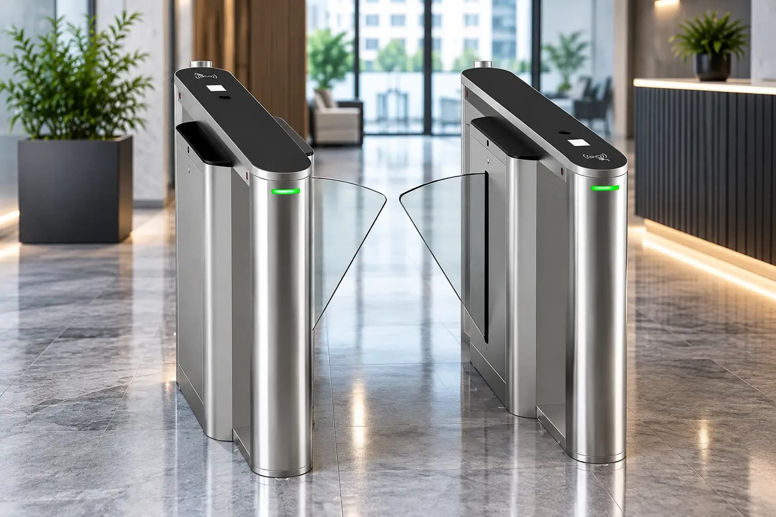
How Does a Flap Barrier Gate Work?
What Is a Flap Barrier Gate?
It is also called a flap barrier turnstile, and in its taller glass-clad lobby form a speed gate. It manages flow at a controlled point: an office reception, a concourse, a plant gate, a campus entrance. It sits in the same family as the swing barrier and the tripod turnstile, and the differences between the three are mechanical rather than conceptual, but the mechanical difference is what determines which device belongs in which room.
The framing that matters most is this: a flap barrier is an access management and detection device, not a physical restraint, and its flaps are light by design. What it delivers is a controlled, auditable decision point where nothing passes until the system has established that it is allowed to, every passage is logged, and anything irregular raises an alarm. The security value is the alarm, the video bookmark and the response procedure acting together, not the panel.
Most of this page is about the question the mechanism raises rather than answers. A device with a short cycle invites a capacity assumption, and that assumption is where most flap barrier projects go wrong. The throughput section below is the longest on the page for exactly that reason.
How Does a Flap Barrier Gate Work?
A flap barrier gate works in five stages. A person presents a credential at the reader, a card, a fingerprint, a face, a code on a phone. The controller validates it against the permitted list, applying any time, direction or anti-passback rule. On a valid result the drive motor retracts both flaps horizontally into the pedestal housings, clearing the lane. The infrared array tracks the person through the lane, reading direction and counting bodies from the order in which beams break and restore. Once passage is confirmed, the flaps extend back across the lane and the event is written to the log.
Present, validate, retract, track, extend. Everything else on this page is detail beneath those five verbs, and the throughput method further down is most usefully understood as the discovery that the first verb, not the third, sets how fast the lane actually moves.
Retraction Versus Rotation: The Difference That Defines the Category
This distinction deserves its own section because it is the source of most confusion in this product family and because every other characteristic of the device follows from it.
Flap barrier flaps retract horizontally into the pedestal. They slide sideways, withdrawing into slots in the housings on either side of the lane, and at the fully open position they are inside the pedestals rather than anywhere in the opening. Swing barrier panels rotate about a vertical axis. They pivot at the pedestal, sweeping through roughly a quarter turn, and at the fully open position they stand alongside the lane rather than inside the housing.
Three consequences follow, and they explain the entire division of labour between the two devices.
- The flap travels a shorter distance and carries less inertia, so the cycle is shorter. A light panel sliding a short distance can be accelerated and stopped quickly; a rigid panel rotating through an arc cannot, because its mass is distributed away from the pivot. This is the whole reason flap barriers are associated with fast-moving entrances.
- A retracting flap must be light enough to withdraw and yield, which caps how substantial it can be. That is why flaps are acrylic or polycarbonate rather than steel, and why the device controls passage rather than restraining it.
- Retraction constrains lane width, because the flap has to fit inside the pedestal. A swing panel has no such limit (it swings clear) which is why wide accessible lanes are typically a swing format and why standard flap lanes will not take a wheelchair or a trolley.
The same difference explains why premium lobby speed gates are a flap variant rather than a swing one. A reception bank is judged on how quickly a stream of arriving people clears it and on how little floor it occupies, and both favour the retracting mechanism. The glass pedestals and quiet drive that distinguish a speed gate are a build specification layered on top of that mechanical choice, not a different operating principle.
Main Components of a Flap Barrier Gate
| Component | Function | What varies between specifications |
|---|---|---|
| Pedestal housings | Cabinets either side of the lane holding the drive assembly, controller, sensor array and the retracted flaps. Commonly stainless steel, with grade selected against the environment. | Internal width, which sets how far the flaps can withdraw and therefore the clear lane width; material grade, which matters where humidity or airborne salt is a factor. |
| Retractable flaps | The moving panels blocking the lane. Usually acrylic or polycarbonate; tempered glass on premium variants. They withdraw into slots in the pedestals rather than rotating open. | Material, thickness and edge profile, all of which bear on mass, on drive requirement and on how the flap behaves on contact with a person. |
| Drive motor and retraction mechanism | A servo or brushless DC motor with a linkage, rack or belt converting rotation into the flaps' horizontal travel. Low flap mass means low inertia, which is what permits a short cycle. | Motor rating against flap mass and cycle count together, and whether holding force and reversal sensitivity are configurable or fixed in firmware. |
| Encoder position feedback | Reports flap position continuously, supporting precise stopping, soft start and soft stop, and obstruction detection by comparing expected against actual travel. | Resolution, and whether obstruction sensitivity is exposed to the installer as a configurable parameter. |
| Controller | The logic of the lane. Accepts reader and sensor inputs, drives the motor, applies the anti-tailgating and direction rules, raises alarms and communicates with the access control platform. | Where the access decision is taken, how many violation types are distinguished, and how the lane behaves if the network link drops. |
| Infrared sensor array | Multiple transmitter and receiver beam pairs at varying heights down the facing sides of both pedestals. The pattern and sequence of broken beams is what the controller reads to determine presence, direction and body count. | Beam pair count, vertical distribution and spacing. This is the specification that decides anti-tailgating quality and the one most often reduced to a single number. |
| Credential reader | Card reader, fingerprint or palm sensor, face terminal, code scanner, or a combination. Mounted on the pedestal top or integrated into its face. | Reader technology, mounting height and angle, which together set presentation time and therefore, as the throughput section explains, the lane's real rate. |
| Direction indicators | Arrow or cross indicators on the pedestal tops showing whether the lane is open in a given direction. | Visibility from the approach distance and whether indication is pictographic rather than text-based, which matters where the user population does not share one language. |
| Alarm | Audible and visual indication on tailgating, wrong-direction entry, forced passage or an unauthorised attempt, normally also raised as an event in the software. | Whether violation types are distinguished in the alarm and the log, and whether tone and volume suit the acoustic environment. |
| Power supply and backup | Low-voltage supply inside the pedestal, with battery or UPS provision where the lane must stay controlled through an interruption. | Input voltage and frequency vary by region; backup duration and whether it is fitted as standard vary by model and specification. |
| Manual release | A mechanism freeing the flaps so the lane can be opened by hand during a power failure or maintenance. | Whether release is automatic on power loss or requires a deliberate action, and whether its operation is itself signalled. |
Pedestal housings and retractable flaps
The pedestal is not simply a cover. Its internal width sets how far the flaps can withdraw and therefore the clear lane width, which is the mechanical reason a standard flap lane is narrow. Its facing surface carries the sensor array, so alignment relative to the opposite pedestal is a functional requirement rather than a cosmetic one. Two pedestals installed slightly out of parallel produce intermittent sensor faults that are routinely misdiagnosed as an electronics problem and chased for months.
Drive motor and the retraction mechanism
Most current models use a brushless DC or servo motor with encoder feedback rather than a simple geared motor. The encoder tells the controller exactly where the flaps are throughout travel, which supports precise stopping, soft start and soft stop so the flaps do not snap open, and obstruction detection by comparing expected travel against actual. The linkage, rack or belt that converts rotation into horizontal travel is the mechanism's distinguishing element and the one whose condition determines how cleanly the flaps meet at the lane centre over time.
Controller and credential reader
The controller holds the open timers, the direction rules, the response to each sensor pattern, the alarm logic and the interface to the wider system. The reader is deliberately separate from it, which is why a lane can be re-fitted from card to face recognition, or made to accept both, without changing the barrier mechanism: the reader simply supplies a validated identity to the same controller input. That separation is also why the reader choice can be revisited later to address a throughput problem, which is unusually convenient given that the reader is normally where the throughput problem lives.
The infrared sensor array
This is the part that makes a flap barrier more than a powered gate, and it is covered in full in the next section.
How Does a Flap Barrier Gate Work Step by Step?
| Step | What happens | How it works |
|---|---|---|
| 1 | A person approaches the lane | The first beams of the infrared array register someone at the entry mouth, and the direction indicator shows whether the lane is open that way. |
| 2 | A credential is presented | A card is tapped, a finger or palm is placed, a face is presented to the terminal, or a code is shown to the scanner. This is the step that sets the lane's real rate. |
| 3 | The credential is validated | The reader passes the identity to the controller or access platform, which checks it against the permitted list along with any time, direction or anti-passback rule. A valid match produces an open command; an invalid one is logged as a denied attempt. |
| 4 | The drive retracts the flaps horizontally | The controller energises the motor, which draws both flaps sideways into the pedestal housings, clearing the lane. This horizontal retraction is the mechanical difference from a swing barrier, whose panels rotate about a vertical axis. |
| 5 | The open position is confirmed | The encoder or a limit position tells the controller the flaps are fully withdrawn, and the motor stops. |
| 6 | The person walks through | Infrared beam pairs break and restore in sequence as the body moves along the lane, and the controller reads that sequence continuously rather than as discrete events. |
| 7 | Passage is analysed | From which beams broke, at what heights and in what order, the controller determines direction, counts the bodies in the lane, and decides whether the passage is a single authorised person or a violation. |
| 8 | Passage is confirmed complete | When the exit-side beams clear and no further body is detected, the controller treats the passage as finished. |
| 9 | The flaps extend back across the lane | The motor drives the flaps out of the pedestals until they meet at the lane centre, ready for the next credential. |
| 10 | The event is logged | The passage (identity, direction, lane, timestamp and any alarm raised) is written to the access control or attendance database. |
If a second person is detected in the lane without a second authorisation, or if someone enters against the set direction, the controller does not complete step 9 normally. It closes the flaps and raises a classified alarm instead, which is the subject of the next section.
How the Infrared Array Determines Direction and Detects Tailgating
The sensor array is the core of the anti-tailgating logic and the single component that most separates a capable lane from a basic one. Along the facing side of each pedestal sits a column of infrared emitters with matching receivers opposite, each pair forming a beam across the lane at a set height. A lane may carry anywhere from a handful of pairs to well over twenty depending on the model. Nothing about any single beam is clever. What the controller does with the whole pattern is.
As a person walks through, their body interrupts beams in a characteristic order (entry-side first, then middle, then exit-side) and beams at torso height break for longer than those at head or knee height. From that pattern the controller derives three things:
- Direction: the order in which beams break tells the controller which way the person is travelling, so entry against a lane set for exit is flagged as wrong-direction passage.
- Body count: one body produces a single continuous block of interruption moving along the lane; two produce a second block before the first has cleared.
- Anomalies: a low break with nothing above it is probably a bag or a trolley; a break that stops mid-lane is probably someone who has turned back.
On a violation the controller closes the flaps and raises the alarm, and the event appears in the software with its own classification so it can be reviewed later against video footage.
Array quality decides anti-tailgating quality. A lane with too few beam pairs, or with all of them clustered at one height, simply cannot resolve a second person following closely behind the first: the two bodies read as one continuous interruption and nothing is flagged. Where anti-tailgating is a genuine requirement rather than a line in a specification, the number of beam pairs and their height distribution deserves at least as much attention as the finish of the pedestal, and the layout should be requested as a drawing rather than accepted as a single number, two products quoting the same count can behave very differently in the same lane.
Flap Materials and Why They Are Chosen
Flaps are usually acrylic or polycarbonate, and the choice is deliberate on two counts rather than incidental.
Mass. A light panel has low inertia, so it can be accelerated and stopped quickly, which is what makes the short cycle possible in the first place. A heavier flap would need a larger drive and would still cycle more slowly, which would remove the device's reason to exist.
Behaviour on contact. A light panel with rounded edges yields rather than injures if it meets a person. That matters in a device closing across a walking route used by children, older people, anyone carrying something and anyone not paying attention, which is to say, in every real entrance. The yielding flap is part of the safety design rather than a compromise in it.
Between the two materials, polycarbonate resists impact better while acrylic is more scratch-resistant and holds optical clarity well in heavy public use. Some models, particularly speed gates for corporate lobbies, use tempered glass flaps for appearance. Glass is heavier and changes the drive requirement, so it is a design choice made at model level rather than a field substitution, fitting glass flaps to a drive rated for acrylic produces exactly the slow degradation described in the maintenance section.
How to Model Throughput and Size a Lane Bank for Any Site
This is the section most entrance projects skip, and skipping it is the reason so many lane banks produce a queue the day they open. The failure is almost never the equipment. It is an arithmetic error made at briefing stage, where a daily headcount was divided by a catalogue rate and the answer was treated as a lane count.
Figures commonly quoted for flap barrier lanes sit in the region of tens of people per minute per lane, but any such figure is approximate and equipment-dependent: it varies with the model, the drive, the controller timing and how the lane is configured. More importantly, it assumes something that real entrances almost never deliver: that people present credentials smoothly and continuously, one after another, without pause. The method below replaces that assumption with observation.
Step 1, Establish the peak arrival profile, not the headcount
The first requirement is a shape, not a number. Two buildings with identical daily occupancy can need completely different lane banks depending on how their people arrive.
- Observe an existing entrance across its whole peak period, recording arrivals in short intervals rather than as a total. The profile that emerges (a sharp spike, a broad plateau, or several smaller waves) is the thing the bank must absorb.
- For a new building, derive the profile from the operating pattern. A single shift start concentrates almost everything into minutes. A staggered or flexible pattern spreads the same population across an hour and may need half the lanes.
- Identify what drives the shape. A transport service arriving on a schedule produces waves rather than a flow, and a bank sized for the average will queue on every wave.
- Record the direction split, since morning inbound and evening outbound peaks are frequently of different heights and different shapes in the same building.
- Record the profile as a series, not a maximum (for example "arrivals in five-minute blocks across the 40-minute morning peak") because the series is what later reveals whether a queue clears between waves or accumulates.
Step 2, Measure credential presentation time, because that is the real constraint
This is the step that distinguishes a working model from a catalogue calculation, and it is the central claim of this page: in an actual entrance the limiting factor is almost never how fast the flaps move. It is how long someone takes to present a credential.
- Time it directly. Stand at an existing lane during the peak and time from a person reaching the reader to the flaps beginning to retract. The spread in that figure is usually wider than the whole mechanical cycle.
- Understand what drives it: finding a card in a bag, positioning a finger correctly, stopping and looking at a face terminal, retrieving a phone, or simply not knowing where the reader is.
- Measure the population you will actually have. A fixed staff population that passes the same lane twice a day becomes fast through familiarity; a visitor or public population never does, and must be modelled at the slower figure.
- Treat the reader choice as a throughput decision: because it is. A method that resolves during the approach outperforms one requiring a deliberate stop, regardless of how quickly the flaps move afterwards.
- Derive the realistic per-lane rate from presentation time plus the mechanical cycle: not from the catalogue figure, and state in the specification that the derived rate is approximate and equipment-dependent.
Step 3, Derive the lane count from observed behaviour
With a profile and a realistic per-lane rate, the lane count becomes arithmetic rather than judgement, and it is usually a larger number than the catalogue calculation produced.
- Apply the realistic rate to the busiest interval of the profile: not to the peak hour averaged out. An entrance that works on average and fails for eight minutes every morning is an entrance that fails.
- Check whether the queue clears between waves. A bank that falls slightly behind during each wave and never recovers produces a queue that grows through the whole peak, which is the characteristic failure of an under-sized bank.
- Set an acceptable queue explicitly (a maximum wait and a maximum queue length) because "no queue" is not achievable and an unstated target is one nobody can design against.
- Compare the result against the catalogue calculation and keep both in the record. The gap between them is the clearest argument available when the lane count is challenged later.
- Re-derive if the reader choice changes: since a change of credential method moves presentation time and therefore moves the lane count.
Step 4, Size accessible lane provision separately
This provision is not a fraction of the throughput calculation and must not be derived from it. It is a separate requirement with a separate basis, and on a flap barrier bank it usually means a different lane format entirely.
- Recognise the constraint: a standard flap lane is narrow, because the flap must fit inside the pedestal when retracted. It will not take a wheelchair, a trolley or large luggage, and no configuration changes that.
- Provide a wide accessible lane alongside: commonly in a swing format since a rotating panel swings clear of the opening rather than withdrawing into it.
- Size the provision from the user mix (wheelchair users, people with assistance animals or walking aids, people with luggage or prams, contractors with equipment, staff moving trolleys) counted as passages rather than as people, since one person moving equipment repeatedly generates many wide-lane passages.
- Place the wide lane on the principal route: not at the far end of the bank behind a planter, where it is technically present and practically a problem.
- Confirm the local requirement before the layout is fixed. Minimum clear widths, required provision and approach space are set jurisdictionally, and a layout satisfying one regime may not satisfy another. This is effectively irreversible once the floor is finished.
Step 5, Allow for the return flow, violations and lanes out of service
Three realities routinely absent from a first model, each of which consumes capacity the model assumed was available.
- The return flow. People leaving during an arrival peak occupy lanes. A bank set entirely inbound at peak forces outbound traffic into a lane that is then unavailable to arrivals, or around the bank entirely.
- Violations and resets. Every tailgating alarm that locks a lane consumes the throughput of everyone behind it. A site expecting a high violation rate (a public population, a poorly briefed one, or one with a lot of accompanied movement) needs either more lanes or a less disruptive alarm response, and that is a decision to take knowingly.
- Denied attempts. An expired or unregistered credential stops a lane for as long as the person takes to realise and move aside, and on a visitor-heavy entrance this is not a rare event.
- Lanes out of service. Maintenance and faults happen. A bank sized exactly to the peak has no capacity on the day one lane is down, which is predictably the day it matters.
- Add the spare lane explicitly and record why: so it survives the first round of design review rather than being removed as surplus.
Step 6, Validate the model against approach and egress space
A correct lane count in the wrong space still produces a queue. The final step tests the model against the room it has to live in.
- Check approach depth. The queue has to stand somewhere, and if it cannot form in front of the bank it will form outside the building or across a circulation route.
- Check clear space beyond the lanes: so people who have passed are not blocked by those waiting for a lift. A bank that clears into a bottleneck behaves exactly like a bank with too few lanes.
- Check the reader position against the approach direction: since a reader people have to turn back for adds to presentation time at every single passage, and presentation time is what the whole model turns on.
- Check indication visibility from the approach distance: because people queueing at a lane set against them is pure lost capacity that no amount of lane count recovers.
- Re-run the model against the final layout: not the concept layout, since circulation changes during design routinely invalidate the assumptions the lane count was built on.
Writing it down: a six-line throughput schedule
The six determinations condense into a schedule short enough to issue with a tender and specific enough that a catalogue rate cannot pass as an answer.
- 1Arrival profile: arrivals in short intervals across the whole peak, by direction, with how the profile was obtained and what drives its shape. Example of a well-formed entry: "Inbound arrivals recorded in five-minute blocks across the 40-minute morning peak at the existing entrance; three distinct waves aligned to a scheduled transport service."
- 2Presentation time: measured time from reaching the reader to flap retraction, for the population that will actually use the lane, with the credential method and the spread observed.
- 3Derived lane rate and lane count: the realistic per-lane rate derived from presentation time plus mechanical cycle, stated as approximate and equipment-dependent; the lane count applied to the busiest interval; the acceptable queue target; and the catalogue calculation retained for comparison.
- 4Accessible provision: number and format of wide lanes, clear width required, position within the bank, the passage count they are sized for, and the local accessibility requirement they were set against.
- 5Allowances: return flow at peak, expected violation and denied-attempt rate with the chosen alarm response, and the spare lane allowed for maintenance and faults, each recorded with its reason.
- 6Spatial validation: approach depth, clear space beyond the lanes, reader position relative to approach direction, indication visibility, and confirmation that the model was re-run against the final layout.
A supplier or designer who can answer all six lines has told you something useful. An answer consisting of a catalogue rate and a division has not.
How Flap Barrier Safety Systems Work
Because the flaps move across a space people occupy, protection is layered, and each layer works by a different mechanism rather than duplicating the others.
- Presence interlock: while the array detects a body in the lane, the controller is inhibited from closing at all. This prevents the close command rather than interrupting one, which is a materially safer arrangement than relying on reversal.
- Obstruction detection: the controller monitors motor load or encoder feedback. A rise in load, or travel stopping short of the expected position, is read as contact and the flaps reverse. Sensitivity is usually configurable and differs between models, so it should be set and tested rather than accepted as delivered.
- Yielding flap material: the light acrylic or polycarbonate panel is itself part of the safety design, limiting the force that can be applied to a person regardless of what the control system does.
- Fire alarm interface: a dry contact from the fire panel drives the flaps to retract and hold open, clearing the escape route. On any lane forming part of an egress path this should be treated as essential and wired at installation rather than added later.
- Power failure behaviour: lanes on an escape route are commonly configured to retract and stay open on loss of power.
The last two are a life-safety decision rather than a default. Fail-safe means the lane opens on alarm or power loss, prioritising evacuation; fail-secure means it stays closed, prioritising containment. Which applies depends on the route, the building's fire strategy and the applicable local rules, and the decision must be agreed with whoever owns life safety for that route and recorded. Fire-egress requirements governing how an entrance control line behaves on alarm differ between jurisdictions, and in several the behaviour is subject to a formal approval process with its own programme implications. Establish the position before the layout is fixed.
Speed Gates and Standard Flap Barriers
The terms overlap and are used loosely, so it is worth being precise. A speed gate works on the same principle as a standard flap barrier, retracting panels, infrared array, the same operating sequence, the same obstruction behaviour. The difference is build and setting rather than mechanism:
- Taller glass pedestals rather than short stainless cabinets, often with the array concealed behind the glass.
- A slimmer profile, so a bank of lanes occupies less floor and reads as part of the reception design rather than as equipment placed in it.
- A quieter drive, because a lobby where people are met and greeted cannot tolerate mechanical noise at every passage.
- Finish-led design: glass, brushed metal, integrated lighting and flush readers.
- Frequently glass flaps, which are heavier than acrylic and therefore paired with a drive rated for them.
A standard flap barrier is built for utility: robust stainless pedestals, straightforward maintenance access, and tolerance of the dust and traffic of a plant gate or a transport concourse. Neither is a better device. They are built for different rooms, and the throughput method above applies identically to both, a speed gate in a busy lobby is just as capable of producing a queue if the lane count came from a catalogue rate.
Where Flap Barrier Gates Are Used
Flap barrier gates appear wherever pedestrian movement must be controlled, counted and recorded, and particularly where the arrival pattern is concentrated. The site types below recur in every region, each with a characteristic throughput profile:
- Corporate campuses and office buildings: reception lanes in speed gate form, with a sharp morning peak and a familiar staff population whose presentation time is short.
- Transport terminals and concourses: high-volume passenger lanes against a public population that cannot be briefed, where presentation time is long and variable and the lane count must reflect that.
- Manufacturing plants and industrial estates: shift entry and exit with attendance capture at the gate, where the entire day's flow concentrates into minutes and the profile is effectively a single spike.
- Logistics and distribution centres: shift-change flow with equipment movement through the same entrance, which makes the separate accessible provision a working requirement rather than a compliance one.
- Hospitals and healthcare campuses: separating restricted clinical areas from public circulation, with wide lanes kept clear for stretchers and equipment.
- Universities and educational campuses: large seasonal variation and a population that changes annually, so the model should be re-run rather than inherited.
- Data centres and high-security facilities: tighter anti-tailgating settings, denser sensor arrays and interlocked lanes, where a higher violation rate is accepted as the trade for the detection standard.
- Government facilities and public institutions: visitor-controlled entry with logging, where denied attempts are frequent enough to belong in the capacity model.
- Stadiums, exhibition centres and event venues: extreme short-duration peaks that dominate every other consideration in the lane count.
- Retail and mixed-use developments: entrance control that must coexist with a designed interior, where the speed gate format is usually the starting point.
TimeWatch supplies, installs and services flap barrier gates, speed gates and associated pedestrian entrance control equipment internationally, and maintains dedicated regional sites for several markets, see the regional guidance below. Lane width, flap material, beam count and cycle behaviour should always be confirmed against the documentation for the specific model being specified.
Integration With Other Systems
A flap barrier lane rarely operates alone. Typical integrations:
- Access control: the credential database governing doors and vehicle gates also governs the lane, so one revocation closes every route at once.
- Time and attendance: the passage event doubles as the attendance record, removing a separate clocking step and a separate queue at shift change.
- Visitor management: a pre-registered visitor receives a code or temporary card the lane accepts for a defined window, with arrival notified to the host.
- Face recognition terminals: hands-free presentation, which addresses the single largest source of lane delay identified in the throughput method above.
- Video surveillance and analytics: footage bookmarked against each lane event, so any tailgating alarm can be reviewed from its log entry rather than searched for by time. This is where the device's security value actually sits.
- Fire alarm systems: automatic retract-and-hold on alarm where the lane forms an escape route, wired and tested at commissioning.
- Occupancy and muster reporting: because the array counts bodies rather than credentials, the lane supports a reasonably accurate live occupancy figure for evacuation roll-call.
- Lift destination control: a validated passage calling a lift to the user's floor, which removes a second queue immediately behind the first.
- Screening equipment: where an entrance includes walk-through metal detection, the lane physically prevents progress until screening is resolved, which is what turns an alarm into a control.
Installation and Site Conditions
Most flap barrier problems trace back to installation and layout rather than to the equipment. The principal considerations:
- Floor flatness and pedestal alignment: pedestals must be level and truly parallel, or opposing sensor pairs fall out of alignment and produce intermittent faults that are easily misdiagnosed as an electronics problem.
- Lane width and accessible provision: a standard flap lane will not take a wheelchair, a trolley or large luggage, so an entrance built entirely from standard lanes has an accessibility problem from day one. Settle this at design stage, from Step 4 of the throughput method, rather than discovering it at handover.
- Queueing and circulation space: approach depth in front of the lanes and clear space behind, validated against the model rather than assumed.
- Cable routing: power, network and reader cabling up through the floor into the pedestal base, in conduit laid before the floor finish. Retrofitting it afterwards is disruptive and usually visible for the life of the floor.
- Reader position: set at a height and angle people find without being told, since a badly placed reader adds to presentation time at every passage and therefore to the lane count required.
- Ambient conditions and environmental derating: a catalogue duty rating assumes reference conditions and a real entrance rarely matches them. Direct sunlight onto the array affects some models, so lanes near a glazed façade need the manufacturer's guidance checked; high ambient reduces permissible duty and stresses electronics; airborne particulates settle on the array's optics and abrade seals; salt-laden coastal air drives the corrosion specification for pedestals and fixings; sub-zero exposure may require heaters; and heavy rainfall at a semi-open entrance demands sealing and drainage attention. State the conditions the lane will actually see and require the supplier to confirm suitability.
- Power supply and backup: stable supply with UPS provision where lane control must survive an interruption, sized against how long the entrance must keep functioning.
- Fire interface wiring: the dry contact from the fire panel pulled and tested during installation, and witnessed where the local approval process requires it.
- Conformity and electrical regimes: machinery safety, electromagnetic compatibility, regional product conformity marking and national wiring rules all differ by jurisdiction, and a mark required in one region is not automatically accepted in another. Identify which regime applies in the country of installation before equipment is selected.
Maintenance Considerations
Flap barriers are electromechanical devices cycling continuously in a public space. Routine attention keeps them dependable:
- Clean the emitter and receiver windows on both pedestals. Dust and fingerprints on the optics are a frequent cause of erratic detection and the fix takes seconds.
- Check pedestal alignment, particularly after any floor work or an impact from a trolley, comparing against the alignment recorded at commissioning.
- Inspect the flaps for scratches, cracks and edge damage, and confirm they still meet cleanly at the lane centre, a drifting meeting point is usually the linkage rather than the flap.
- Verify the drive runs smoothly through full travel with no binding at either end, and listen for changes in sound, which usually precede a failure.
- Test obstruction reversal deliberately, with a soft object, at the configured sensitivity, and record the result.
- Test the fire alarm interface during scheduled drills and confirm the lane behaves as the fire strategy requires.
- Confirm the manual release operates, before it is needed.
- Review alarm logs. A rise in tailgating alarms at one lane usually points to a sensor or layout problem rather than a change in behaviour.
- Review throughput data against the model. Passage counts per lane across the peak will show whether the bank is still performing as designed, a population change, a reader change or a circulation change can invalidate the original model without anyone touching the equipment.
- Set service intervals from passage count and environment rather than a fixed calendar, since a busy public lane and a low-traffic office lane age at very different rates.
Benefits and Limitations
Benefits
- A short cycle relative to rotating-arm and swinging-panel devices, because the flaps retract rather than sweep through an arc.
- Anti-tailgating and direction detection through the infrared array, with each violation classified, alarmed and logged.
- A complete audit trail by identity, direction and time, usable for attendance and live occupancy reporting.
- Reader-agnostic: card, fingerprint, face or code, changeable without altering the mechanism, which also means a throughput problem can be addressed without replacing the lanes.
- In speed gate form, an entrance control device that suits a designed reception rather than fighting it.
- A slim footprint, so a bank of lanes occupies less floor than equivalent capacity in other formats.
- Body counting at the array supports an occupancy figure for evacuation roll-call that credential counting alone cannot provide.
Limitations and considerations
- A flap barrier controls passage; it does not physically restrain. The flaps are light by design and a determined person can force or vault them. The security value comes from the barrier, the alarm, the video bookmark and a defined response procedure acting together, the device alone is not the control.
- Lane width is a real constraint. Standard lanes do not take wheelchairs, trolleys or large luggage, because the flap must fit inside the pedestal when retracted, so a wide accessible lane is normally required alongside in a different format.
- Anti-tailgating performance varies widely with array density and height distribution. Too few beams, or all of them at one height, and a close follower is not detected at all.
- Quoted throughput is not achieved throughput. Credential presentation time, not flap speed, sets the real rate, and any figure quoted anywhere (including one derived by the method on this page) is approximate and equipment-dependent.
- Flap surfaces show wear in heavy public use. Scratching is cosmetic but visible, and replacement panels should be planned for rather than treated as a fault.
- Accessibility and fire-egress requirements differ by jurisdiction and must be established before the layout is fixed, since both are effectively irreversible once the floor is finished.
- Exact behaviour depends on the equipment. Cycle time, sensor count, obstruction sensitivity, fail-state configuration and integration options vary by model, controller, firmware and site configuration, and should be confirmed against the documentation for the equipment being specified.
Flap Barrier vs Swing Barrier vs Tripod Turnstile
| Flap barrier | Swing barrier | Tripod turnstile | |
|---|---|---|---|
| Mechanism | Flaps retract horizontally into the pedestal housings, withdrawing out of the opening entirely | A rigid panel rotates about a vertical axis, sweeping clear of the lane | Three horizontal arms rotate about a hub; the user pushes through one segment |
| Why the cycle differs | Short travel and low flap mass, so acceleration and stopping are quick | Mass distributed away from the pivot and an arc to sweep, so the cycle is longer | The user supplies the movement, so the pace is set by the person rather than a drive |
| Accessibility | Standard lanes are narrow because the flap must fit inside the pedestal; a wide accessible lane is normally added alongside | Can be made wide, since the panel swings clear; commonly serves as the accessible lane in a bank | Not accessible; a fixed narrow aperture that no configuration widens |
| Physical robustness | Light flaps designed to yield on contact; can be forced or vaulted | Heavier panels, somewhat more resistant, still not a restraint | Mechanically the most resistant of the three, though it remains waist height |
| Typically suited to | Lobbies, campuses and concourses where concentrated arrival peaks and a slim footprint govern the design | Entrances needing a wide lane and mixed pedestrian, trolley and equipment traffic | Industrial gates, stadiums and rough-duty high-volume entries |
These are not better and worse versions of one another. A flap barrier is chosen for a short cycle and a slim footprint, a swing barrier for lane width and mixed traffic, a tripod turnstile for durability in rough conditions. Many sites use more than one type on the same entrance, which is precisely what Step 4 of the throughput method produces, since the accessible provision usually calls for a different format from the lanes carrying the volume.
Regional Guidance: India, Saudi Arabia and the UAE
This page is written to be useful anywhere, which means it deliberately avoids national specifics. Local accessibility rules, local fire-egress approval processes, local installer requirements, local availability and local environmental conditions all differ, and generic advice on those subjects is worth less than none.
For three markets, TimeWatch maintains dedicated regional sites with locally relevant versions of this guidance, local product availability and local support arrangements. If you are specifying in one of them, start there rather than here:
- India: timewatchindia.com, How does a flap barrier gate work?
- Saudi Arabia: timewatcharabia.com, How does a flap barrier gate work?
- United Arab Emirates: timewatchuae.com, How does a flap barrier gate work?
Readers elsewhere are in the right place. The mechanism, the array explanation and the six-step throughput method on this page are written to be applied to any location, what you supply is the arrival profile, the measured presentation time, the user mix and the local accessibility and egress requirements, and the method does the rest.
Frequently Asked Questions
How does a flap barrier gate open?
When a valid credential is read, the controller sends an open command to the drive motor, which retracts both flaps horizontally into the pedestal housings either side of the lane. The flaps slide away into the pedestals rather than swinging through an arc, which is what makes the cycle short. The infrared array then tracks the person through the lane, and once passage is confirmed the flaps extend back across the lane and the event is logged.
What is the difference between a flap barrier and a swing barrier?
The difference is mechanical and everything else follows from it. A flap barrier retracts its flaps horizontally into the pedestals, so they withdraw out of the opening entirely. A swing barrier rotates a rigid panel about a vertical axis, so it sweeps clear of the lane instead. Retraction means shorter travel and lower mass, which gives the flap barrier a shorter cycle; rotation means the panel does not have to fit inside the pedestal, which is why wide accessible lanes are usually a swing format.
How many people per minute can a flap barrier handle?
Figures commonly quoted sit in the region of tens of people per minute per lane, but any such figure is approximate and equipment-dependent, varying with the model, the drive, the controller timing and the configuration. It also assumes credentials are presented smoothly and continuously, which real entrances rarely deliver. In practice the limiting factor is how quickly people find their card or present their face, not how fast the flaps move, so lane count should be sized from observed peak behaviour rather than from a catalogue rate.
How do I work out how many lanes an entrance needs?
Record the arrival profile in short intervals across the whole peak rather than taking a daily headcount, since the shape of the peak matters as much as its height. Then measure credential presentation time directly at an existing lane, because that is usually the binding constraint, and combine it with the mechanical cycle to get a realistic per-lane rate. Apply that rate to the busiest interval, add allowances for the return flow, violations and a lane out of service, and size the accessible provision separately.
Why is there a queue at gates that were supposed to be fast?
Almost always because the lane count came from a catalogue rate rather than from observed behaviour. A quoted rate assumes people present credentials continuously, one after another, with no pause. In a real entrance someone is searching a bag, positioning a finger or stopping to look at a terminal, and those seconds are longer than the whole mechanical cycle. A bank that falls slightly behind on each arrival wave and never recovers produces a queue that grows through the entire peak.
How does a flap barrier detect tailgating?
An infrared sensor array runs down the facing sides of both pedestals, with multiple beam pairs at varying heights. As a person walks through, the controller reads which beams break and in what order, and from that pattern works out direction of travel and counts the bodies in the lane. One body produces a single continuous block of interruption moving along the lane; a second produces another block before the first has cleared. If a second person is detected without a second authorisation, the flaps close and a classified alarm is raised.
What are flap barrier flaps made of?
Usually acrylic or polycarbonate. Both are light, which keeps inertia low so the flaps can be accelerated and stopped quickly, and both yield rather than injure on contact, a deliberate part of the safety design in a device closing across a walking route. Polycarbonate resists impact better while acrylic holds optical clarity well under heavy use. Some models, particularly speed gates for corporate lobbies, use tempered glass flaps for appearance, which are heavier and paired with a drive rated for them.
Can a flap barrier stop an intruder?
No. A flap barrier controls passage but does not physically restrain. The flaps are deliberately light so they yield on contact, and a determined person can force or vault them. It is an access management and detection device, and its security value comes from the barrier working together with the alarm, the video bookmark it creates and a defined response procedure. Where a physical boundary is genuinely required, a full height turnstile or a secured door is the appropriate equipment.
Are flap barriers wheelchair accessible?
Standard flap barrier lanes are narrow and will not take a wheelchair, a trolley or large luggage, because the flap has to fit inside the pedestal when retracted. An entrance built entirely from standard lanes therefore has an accessibility problem from day one. Most installations pair several standard lanes with at least one wide accessible lane, commonly in a swing format since a rotating panel swings clear of the opening. Minimum clear widths and required provision are set jurisdictionally and should be confirmed before the layout is fixed.
What is the difference between a flap barrier and a speed gate?
They work on the same principle and follow the same operating sequence; the difference is build and setting. A speed gate has taller glass pedestals, a slimmer profile and a quieter drive, and is designed for a reception that is part of the architecture. A standard flap barrier uses shorter stainless steel pedestals built for utility and easier maintenance access at a plant gate or a transport concourse. Both are sized by the same throughput method.
What happens to a flap barrier in a fire or a power failure?
Where the lane forms part of an escape route it is normally configured to retract the flaps and stay open on fire alarm or power failure, so evacuation is not obstructed, driven by a dry contact from the fire panel. Whether a lane is set fail-safe or fail-secure is a life-safety decision to be agreed with whoever owns the fire strategy and recorded, not left at a default. Fire-egress requirements for entrance control lines differ between jurisdictions and are subject to a formal approval process in several.
